Manufacturing Process: Metal Injection Molding (MIM)
What is Metal Injection Molding (MIM)?
Metal Injection Molding (MIM) merges the precision of plastic injection molding with the strength and durability of metal. It’s the preferred manufacturing process for creating small, complex metal parts that would be challenging or costly to produce using traditional methods such as machining or casting. MIM is widely used in industries that demand high-performance metal components, including medical devices, electronics, firearms, and automotive.
MIM offers significant advantages over conventional metalworking techniques. It allows for the production of parts with intricate geometries and tight tolerances while using a wide variety of metals, including stainless steel, titanium, and other high performance alloys. The process is particularly cost-effective for making small parts in large volumes, as it eliminates much of the waste and manual labor associated with traditional methods such as machining.
Despite its strengths, MIM poses unique challenges, such as controlling dimensional changes during the sintering process. Like plastic injection molding, MIM requires precise control over materials, tooling, and process parameters to ensure high-quality results.
The Metal Injection Molding Process
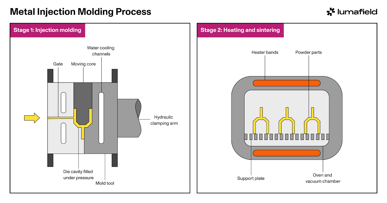
The MIM process involves the following stages:
- Feedstock Preparation: MIM begins by blending fine metal powders with a thermoplastic binder to create a homogenous feedstock. The binder helps the metal powder flow into the mold and holds it in place during the injection molding stage. This feedstock is then granulated into small pellets for easy handling.
- Injection: The metal-binder mix is injected into a mold, similar to plastic injection molding. This mold is designed to create the rough shape of the final part. At this stage, the part is known as a “green part.” The injection process is critical because it determines the accuracy of the part’s geometry and internal features.
- Debinding: After molding, the binder must be removed to leave behind just the metal. This step, known as debinding, is achieved through a combination of thermal or solvent-based processes. The result is a porous structure called a “brown part,” which still requires further densification.
- Sintering: The brown part is placed in a furnace and heated to just below the melting point of the metal, causing the metal particles to bond together. During sintering, the part shrinks and densifies, achieving its final dimensions and mechanical properties. This stage is critical to achieving the part’s strength, hardness, and accuracy.
- Post-Processing (Optional): Depending on the application, the sintered part may undergo additional processes such as machining, heat treatment, or surface finishing to meet specific tolerances or performance standards.
Design Considerations for Metal Injection Molding
Designing parts for MIM requires a deep understanding of both the injection molding and metal sintering processes to ensure that parts meet their required specifications while remaining cost-effective.
- Shrinkage Control: A key consideration in MIM is the shrinkage that occurs during sintering. Parts typically shrink by 15-20% as the metal particles fuse together. Designers must account for this shrinkage in the initial mold design to ensure the final part meets dimensional requirements.
- Wall Thickness: Uniform wall thickness is essential for ensuring consistent material flow during injection and reducing the risk of defects. Thin walls can lead to incomplete filling, while excessively thick sections may result in warping during sintering.
- Draft Angles: As with plastic injection molding, incorporating draft angles allows for easier ejection of the green part from the mold. Proper draft angles also reduce the risk of damage to delicate features during the ejection process.
- Complex Geometries: MIM is well-suited for creating complex shapes that would be difficult or costly to machine. However, designers must be mindful of features like undercuts, threads, and sharp corners, which can complicate both the molding and sintering stages.
- Post-Sintering Considerations: Parts that require tight tolerances or enhanced surface finishes may need post-sintering operations, such as machining or polishing. Designers should consider these additional steps during the initial design phase to ensure the final part meets performance standards without excessive post-processing.
How Industrial CT Can Improve Metal Injection Molding
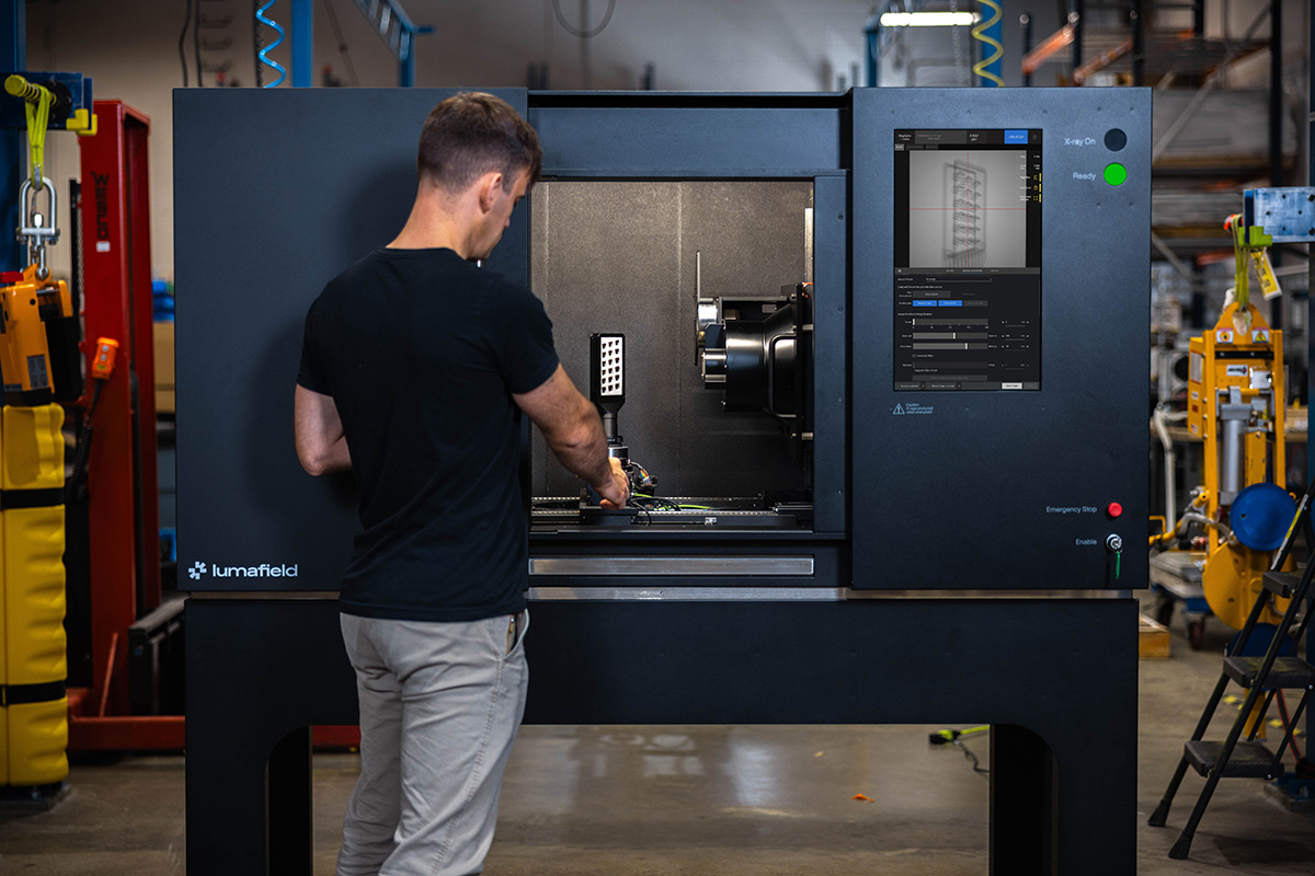
Industrial computed tomography (CT) scanning plays a crucial role in optimizing MIM processes by providing detailed, non-destructive insights into the internal structures of metal parts.
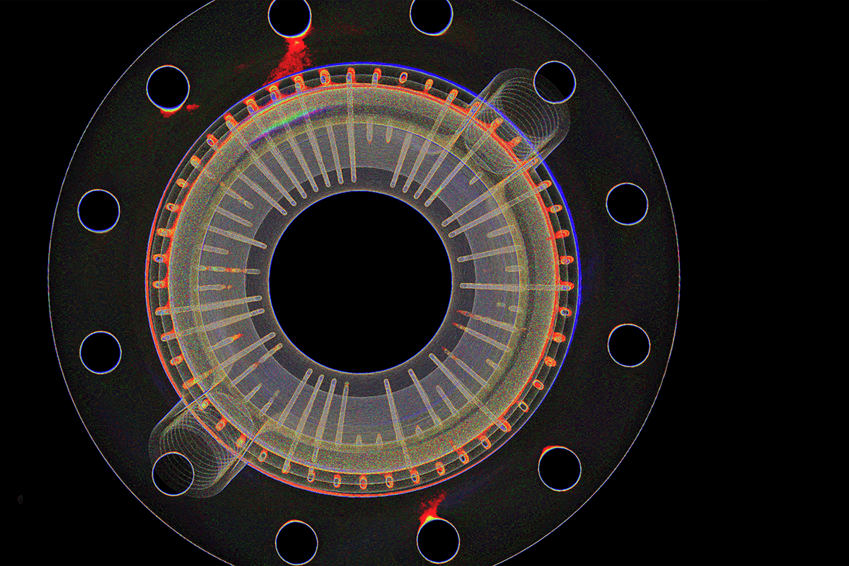
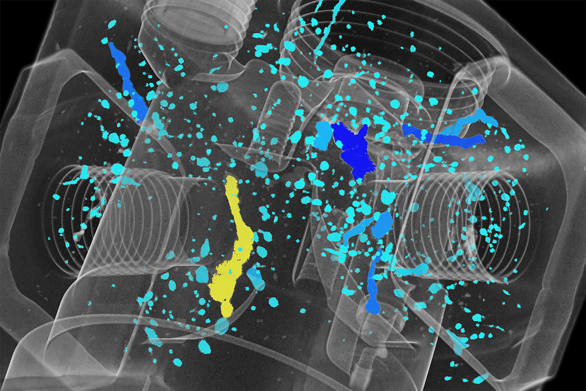
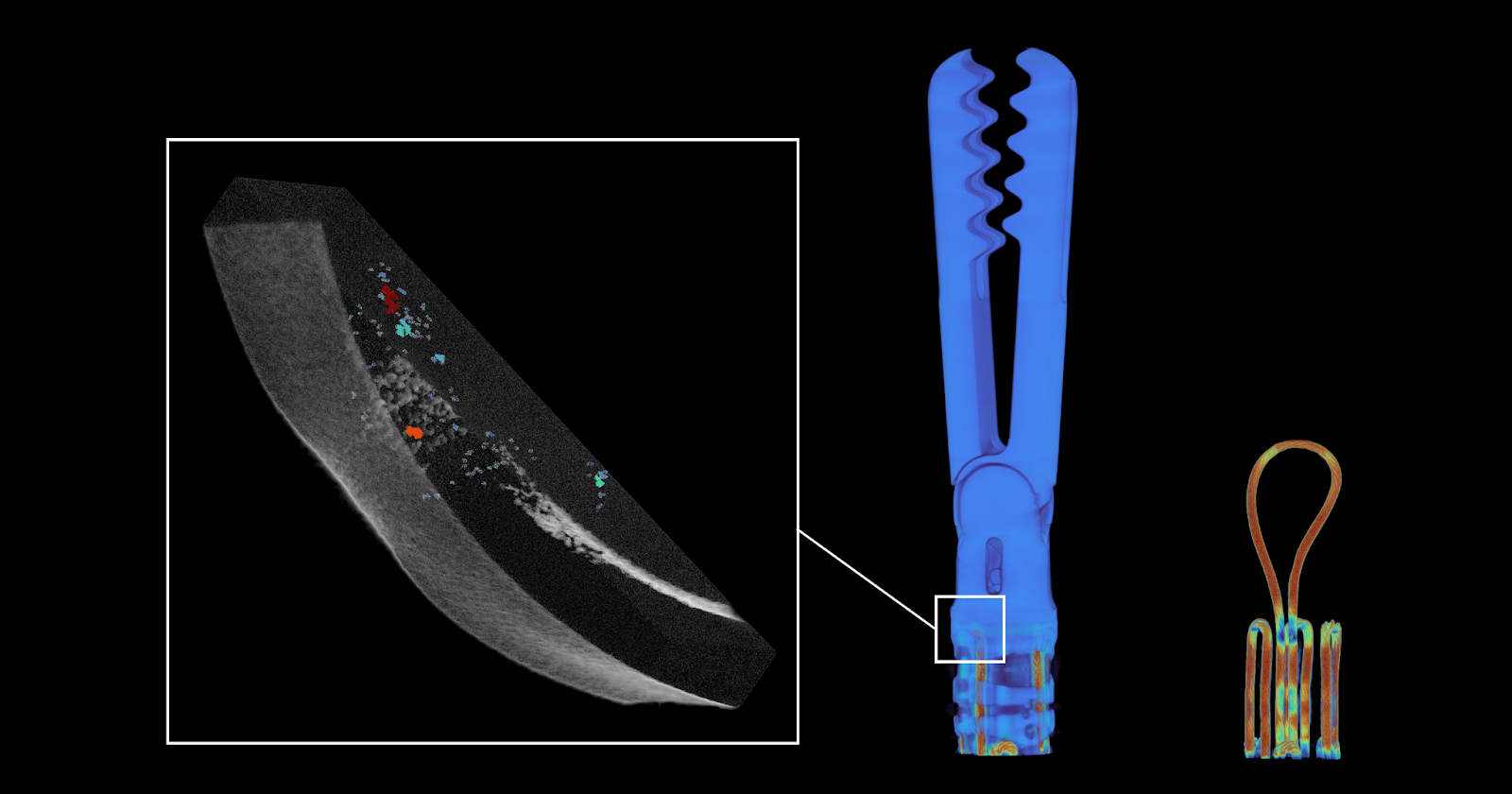
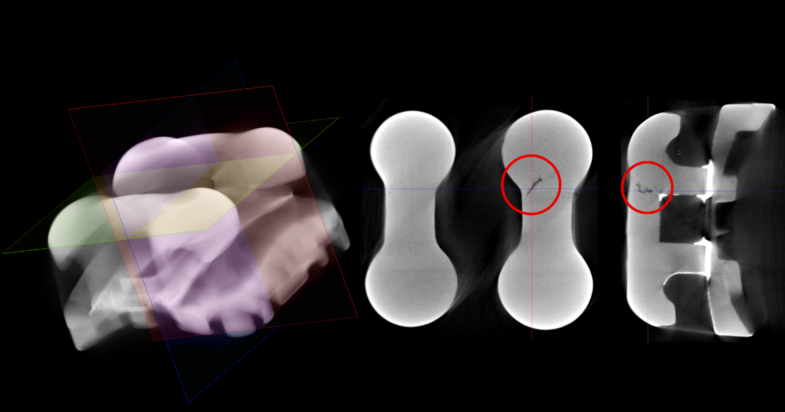
- Internal Defect Detection: In MIM, where fine metal powders are used, internal defects like porosity, voids, or micro-cracks can occur during both the injection and sintering processes. Industrial CT scanning provides a non-destructive method to inspect the internal structure of parts, detecting defects early in production. This is particularly critical in MIM since hidden defects can significantly impact the mechanical properties and longevity of small, precision-engineered metal components.
- Dimensional Stability Assessment: The sintering stage in MIM leads to material shrinkage and potential warping, which can affect part dimensions. CT scanning enables highly accurate measurements of both internal and external geometries, helping manufacturers verify that parts meet design tolerances after sintering. This ensures dimensional consistency, crucial for MIM parts used in industries like aerospace or medical devices where precision is key.
- Process Optimization and Material Flow Analysis: MIM requires precise control over material flow and particle distribution. CT scanning allows manufacturers to visualize how metal particles are distributed within the mold and identify any inconsistencies in material flow or density during sintering. This helps optimize process parameters, such as molding pressure, injection speed, or sintering temperature, leading to improved part quality and more efficient production.
- Prototype Validation and Mold Verification: For MIM, validating the mold and early prototypes is essential before scaling production. CT scans provide a comprehensive view of the internal structure of prototypes, allowing manufacturers to confirm that molds are producing accurate parts and that sintering processes are correctly tuned. This early-stage validation helps reduce the risk of defects in mass production and avoids costly redesigns or tooling modifications later.
- Failure Investigation: When MIM parts fail during testing or usage, CT scanning is an indispensable tool for root cause analysis. By providing detailed imaging of the internal structure, manufacturers can identify specific defects—whether they result from improper sintering, material inconsistencies, or hidden cracks—and take corrective action to improve future production runs.
- Minimizing Waste and Enhancing Sustainability: MIM involves expensive raw materials, and post-sintering processing is time-consuming. By using CT scans to detect defects early, manufacturers can reduce scrap rates, rework, and material waste. This not only improves overall production efficiency but also enhances sustainability by minimizing the need for excess material and energy consumption.
Conclusion
Metal Injection Molding (MIM) is a powerful process that combines the flexibility of injection molding with the strength and durability of metals. By enabling the production of small, complex parts with tight tolerances, MIM serves critical applications across industries. However, the process presents unique challenges, particularly during sintering, where dimensional changes and internal defects can arise.
Industrial CT scanning addresses these challenges by providing manufacturers with detailed, non-destructive insights into part quality and process efficiency. By using CT to detect defects, verify dimensions, and optimize processes, manufacturers can improve the quality of MIM parts, reduce waste, and achieve higher production efficiency.