Using Industrial X-ray CT for GD&T
At Lumafield, we believe engineers should be able to see, understand, and measure every detail of their parts without switching between tools or waiting hours for inspection data. With the introduction of Auto-Dimensioning, a new suite of capabilities that brings Geometric Dimensioning and Tolerancing (GD&T) into Lumafield’s Neptune and Triton industrial X-ray CT scanners, we’re excited to shine a light on this foundational part of modern manufacturing. Auto-Dimensioning, coming in early 2026 to Voyager, Lumafield’s AI-powered 3D analysis platform, makes it easier than ever to apply GD&T principles to complex parts—both inside and out.
What is GD&T?
Consider an e-chain, an injection-molded plastic cable carrier used to guide and protect cables and tubings in moving machinery. Each link in an e-chain must be manufactured to extremely tight tolerances so it can pivot smoothly, maintain consistent spacing, and handle thousands of cycles without binding or separating. If the hinge geometry, pin diameter, or alignment of the molded components is even slightly off, the chain can jam, wear unevenly, or fail under stress. Imagine a production line going down because a cable carrier link doesn’t move freely; even small geometric errors could cause major downtime and costly repairs.
This is where GD&T comes in. GD&T is the universal language engineers use to define how parts should fit and function in the real world. Rather than relying only on linear dimensions, GD&T describes the shape, orientation, and position of every feature relative to others. It ensures that parts not only meet their size requirements but also assemble and perform correctly. Without GD&T, two components might technically “meet spec” yet still fail to fit together or function properly because their geometry isn’t controlled precisely enough.
The critical features of this e-chain are the cylindrical protrusions and mating holes that connect each link, forming the complete energy chain assembly. By applying the GD&T control of “True Position” to these features, we ensure precise alignment between links, maintaining the designed minimum bend radius that protects the internal cables and tubing. Additionally, by controlling the “Parallelism” of each link’s flanges, we guarantee smooth assembly, consistent clearance, and low-friction movement. These are all essential for achieving the rated service life of the e-chain. In short, GD&T enables each manufactured link to fit together seamlessly and perform reliably throughout its operational lifetime.

Common GD&T tools
Verifying GD&T features is a critical part of ensuring that parts meet design intent. Engineers traditionally rely on a combination of manual tools and specialized metrology equipment to inspect dimensional and geometric tolerances. Each method serves a purpose, but all come with trade-offs in accuracy, speed, and accessibility.
Manual Instruments
For basic dimensions such as diameters, lengths, or hole spacing, manual instruments like calipers, micrometers, dial indicators, and height gauges may satisfy requirements. These tools are simple and effective for quick checks, but they lack the precision and repeatability needed for more complex GD&T features such as true position, flatness, or profile control.
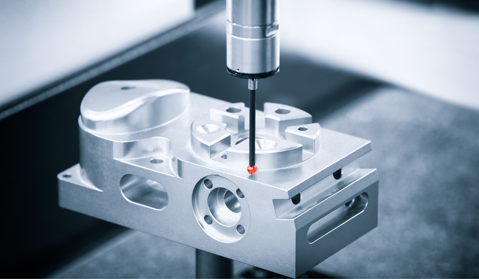
Coordinate Measuring Machines
For higher-precision measurements, Coordinate Measuring Machines (CMMs) are the standard choice. A CMM uses a tactile probe to record points on a part’s surface and builds a geometric model that can be compared to the CAD design. Engineers then calculate tolerances such as cylindricity, perpendicularity, and profile of a surface from these data points. Although highly accurate, CMMs are slow to program, require skilled operators, and are limited to external or line-of-sight surfaces.
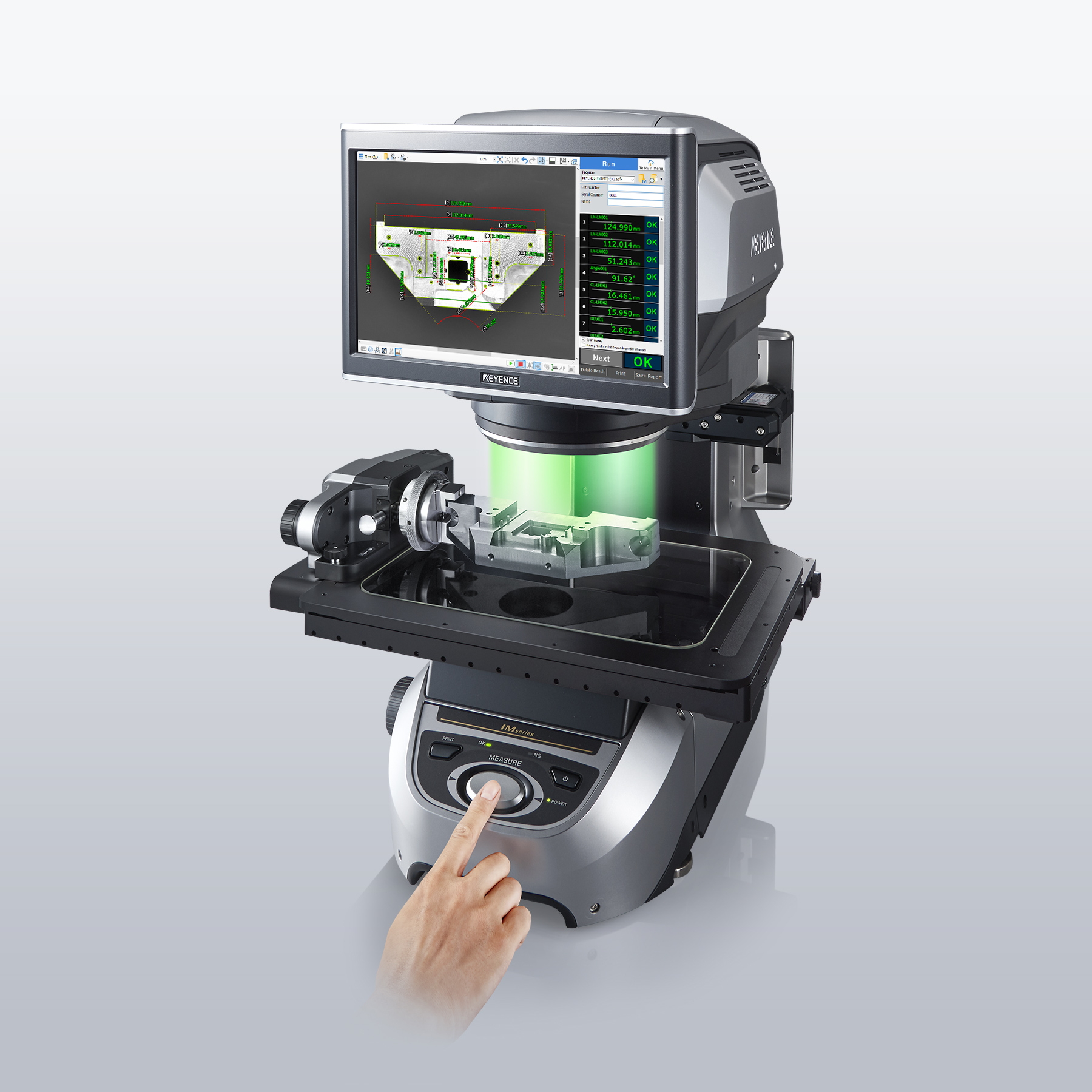
Optical Measuring Machines
Optical Measuring Machines (OMMs) and 3D surface scanners offer non-contact alternatives by using cameras or laser light to capture surface geometry. These systems are fast and useful for delicate parts, but they cannot easily measure internal features, transparent materials, or complex assemblies. As a result, verifying GD&T for parts such as injection-molded housings, connectors, or mechanical assemblies like the e-chain above often requires multiple setups and instruments to build a complete dimensional picture.
GD&T with Industrial X-ray CT
Industrial CT scanners make it possible to capture an entire part in three dimensions, including both internal and external geometry. Unlike CMMs or OMMs, CT scanning is not limited by line of sight or material properties, which means even transparent, flexible, or intricate components can be fully measured and analyzed.
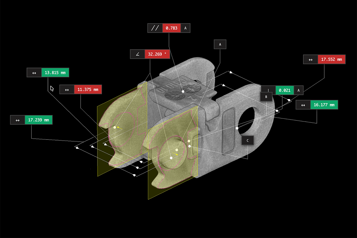
Lumafield’s Auto-Dimensioning analyzes CT scan data to identify geometric features such as planes, cylinders, cones, and holes. From these, it automatically defines datums and reference frames and applies standardized GD&T callouts directly to the 3D model. Engineers can then verify form, orientation, and location tolerances such as flatness, perpendicularity, concentricity, and true position. Because the analysis works with both volumetric data and surface meshes, it measures internal and external features together within a consistent coordinate system.
The future of GD&T
Geometric Dimensioning and Tolerancing has long been the foundation of precision manufacturing, defining how parts fit and function in the real world. Yet traditional measurement tools often capture only part of the picture, leaving internal features and complex geometries difficult to verify. Industrial X-ray CT closes that gap by revealing the complete structure of a part, inside and out, and by allowing engineers to measure every surface relative to a consistent coordinate system.
With Voyager’s Auto-Dimensioning, GD&T principles can now be applied directly to CT data, creating a single workflow for analyzing, validating, and documenting dimensional accuracy. Engineers gain a deeper understanding of how parts are made and how they perform, from molded links in an e-chain to intricate assemblies with hidden features.
By integrating GD&T and CT scanning, measurement becomes more than a checkpoint at the end of production and becomes an active part of design, process control, and continuous improvement. The result is better data, better decisions, and more reliable products across every stage of development.