A deep dive into DMLS 3D printing with industrial CT
Introduction to DMLS
DMLS, or direct metal laser sintering, is a 3D printing process that builds metal parts by melting metal powder with a laser. It's similar to selective laser sintering, a polymer 3D printing process. DMLS printers allow engineers to create parts with complex geometries that would be difficult to cast or machine, but designing for DMLS is tricky, and these machines can introduce critical flaws that lead to part failure.
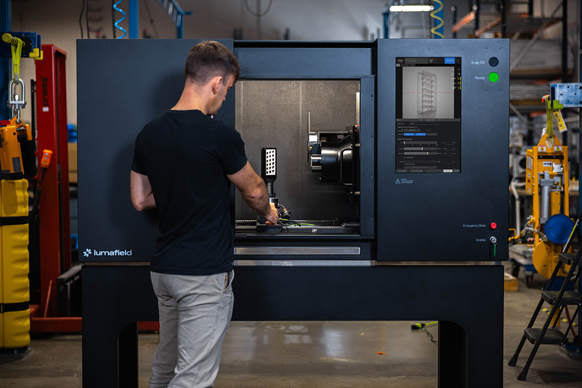
Industrial X-ray CT scanners are ideally suited to 3D printing workflows; they can quickly inspect both internal and external features and validate designs for production. Here we check for some common DMLS issues with a Lumafield Neptune CT scanner.
Explore this scan in Voyager by creating a free account.
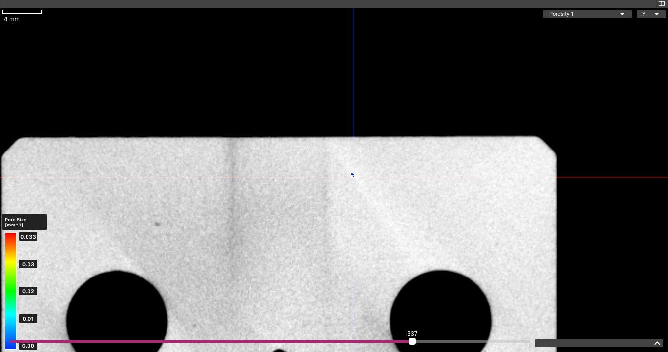
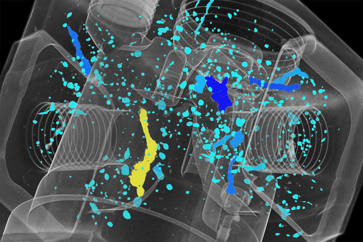
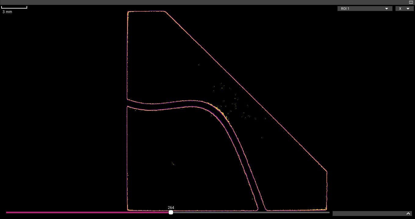
Trapped powder
Powder-bed 3D printing processes like DMLS and SLS require post-processing to remove unfused powder from printed parts. In many cases, this post-processing requires painstaking manual work, and an invisible pocket of trapped powder could make a part unsuitable for its intended application.
Here, we notice a small amount of leftover powder that was not cleared during post-processing. In a production environment, this part might be returned for additional processing to remove the remaining powder, then re-scanned to ensure quality.
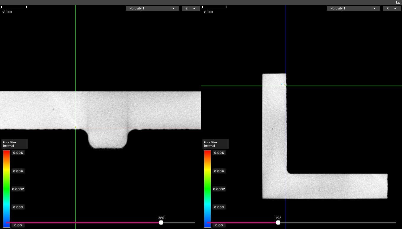
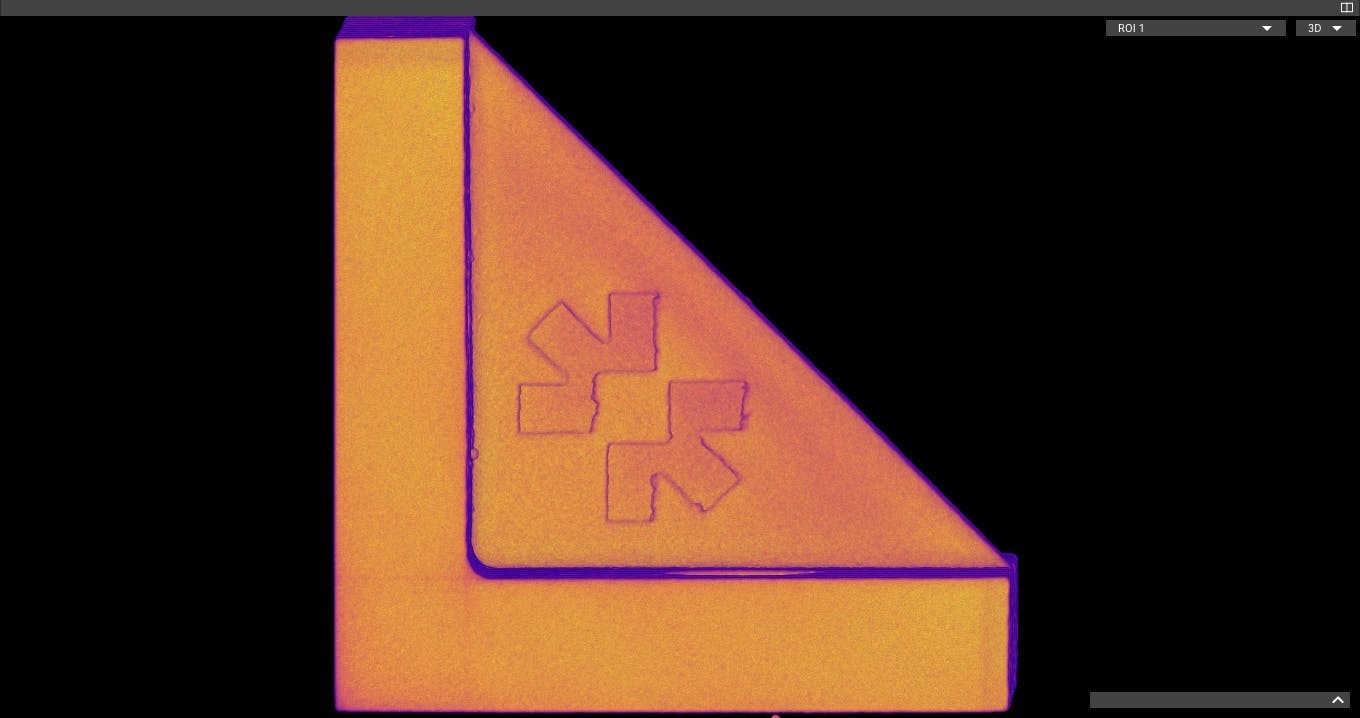
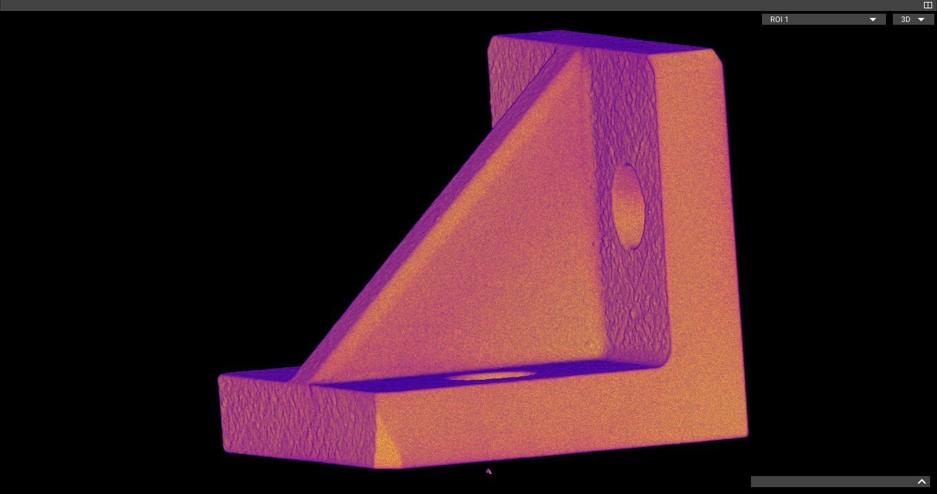
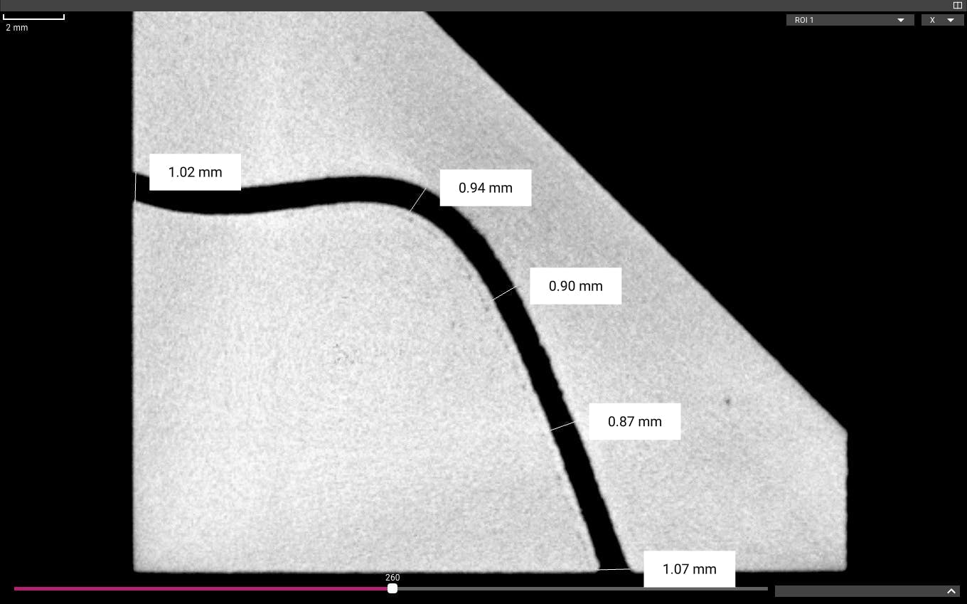
Dimensional accuracy
Thermal 3D printing processes can introduce warping and other problems with dimensional accuracy, especially on fine internal features that can't be inspected visually. In this case, our internal channel varies from its 1mm nominal diameter by as much as 13%.
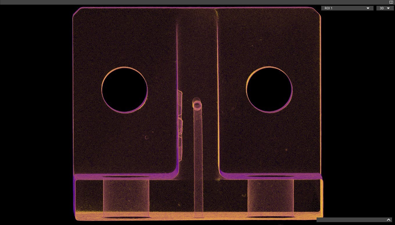
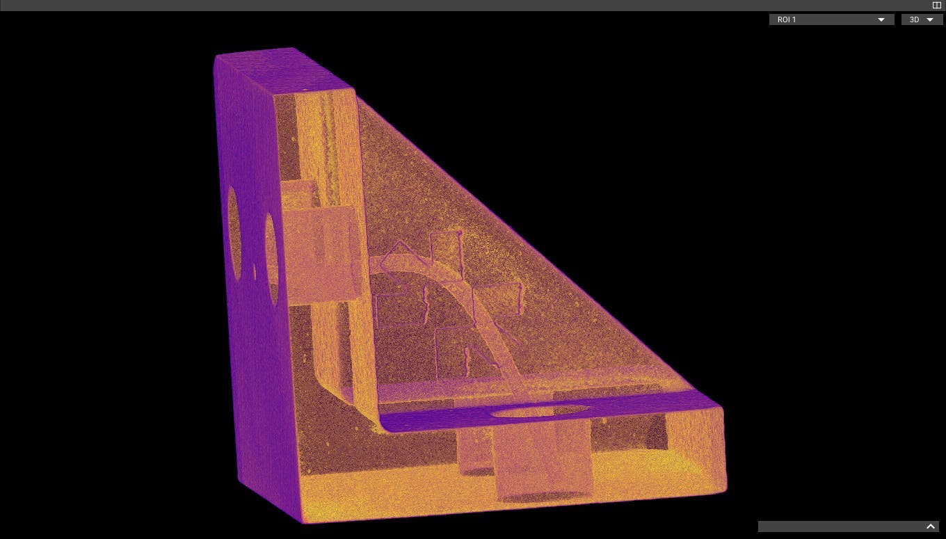
Pores and voids
Like casting and molding, thermal 3D printing processes can leave invisible pores and voids inside parts, increasing the probability of mechanical failure. Our CT scan confirms that this part is largely solid, but these 2D slices show a pore in the upper half of the bracket, close to where the channel starts.