FREE WHITE PAPER

Heading

Date
This is some text inside of a div block.
FREE WHITE PAPER

Heading 1

Heading 2

Heading 3

Heading 4

Heading 5
Heading 6

Lorem ipsum dolor sit amet, consectetur adipiscing elit, sed do eiusmod tempor incididunt ut labore et dolore magna aliqua. Ut enim ad minim veniam, quis nostrud exercitation ullamco laboris nisi ut aliquip ex ea commodo consequat. Duis aute irure dolor in reprehenderit in voluptate velit esse cillum dolore eu fugiat nulla pariatur.

Block quote

Ordered list

  1. Item 1
  2. Item 2
  3. Item 3

Unordered list

  • Item A
  • Item B
  • Item C

Text link

Bold text

Emphasis

Superscript

Subscript

Heading 1

Heading 2

Heading 3

Heading 4

Heading 5
Heading 6

Lorem ipsum dolor sit amet, consectetur adipiscing elit, sed do eiusmod tempor incididunt ut labore et dolore magna aliqua. Ut enim ad minim veniam, quis nostrud exercitation ullamco laboris nisi ut aliquip ex ea commodo consequat. Duis aute irure dolor in reprehenderit in voluptate velit esse cillum dolore eu fugiat nulla pariatur.

Block quote

Ordered list

  1. Item 1
  2. Item 2
  3. Item 3

Unordered list

  • Item A
  • Item B
  • Item C

Text link

Bold text

Emphasis

Superscript

Subscript

Download Resource
Thank you! Your submission has been received!
Oops! Something went wrong while submitting the form.

Inspecting FDM 3D prints with industrial CT

Edited by
Date
August 1, 2022
Introduction to FDM

Fused deposition modeling (FDM) is one of the earliest forms of 3D printing. FDM printers use one or more heated nozzles to melt and extrude thermoplastic filament, depositing it layer by layer to form a part. FDM printers are common in a wide range of applications, from hobbyist workshops to heavy industry.

As with all 3D printing processes, getting the best results from FDM requires some specialized design knowledge and an understanding of its limitations. An industrial X-ray CT scanner can quickly pinpoint invisible features in FDM prints, including some that can cause failures.

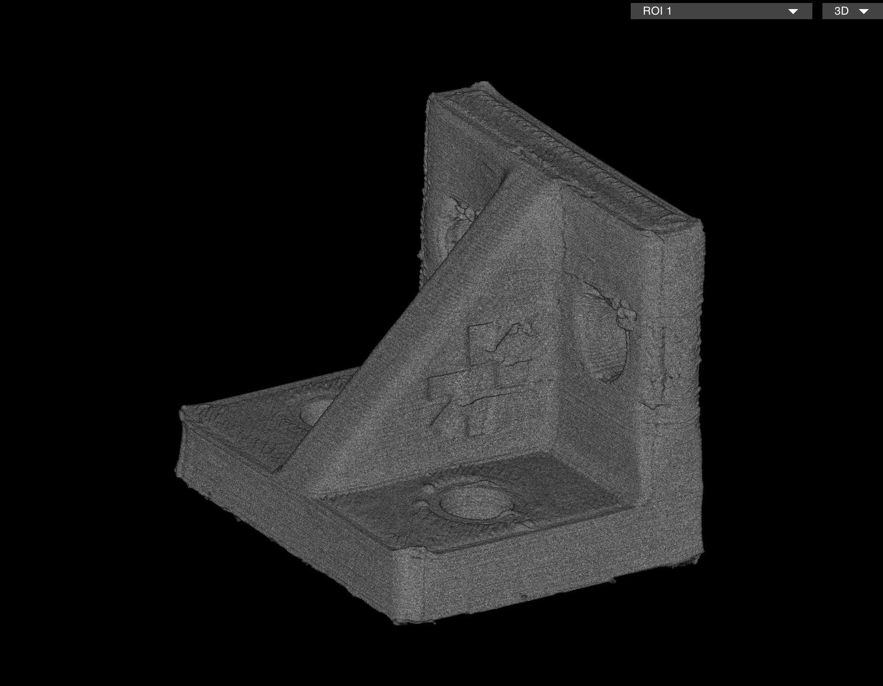
Explore this CT scan in Voyager by creating a free account.
Internal supports

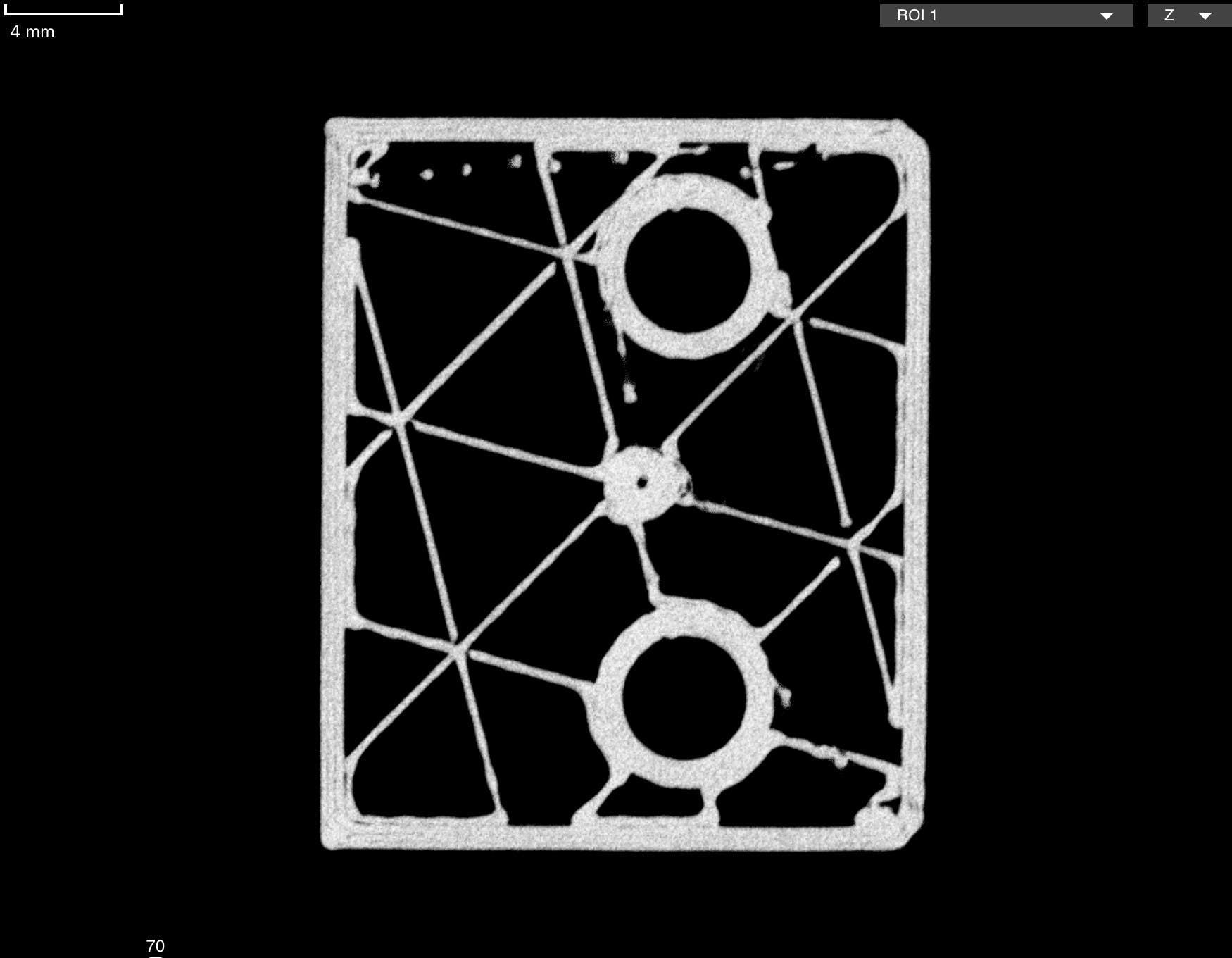
In order to save time and material, operators often configure FDM printers to fill large volumes with a sparse pattern. Here our CT scan reveals a honeycomb lattice inside the solid walls of the part.
Layer quality

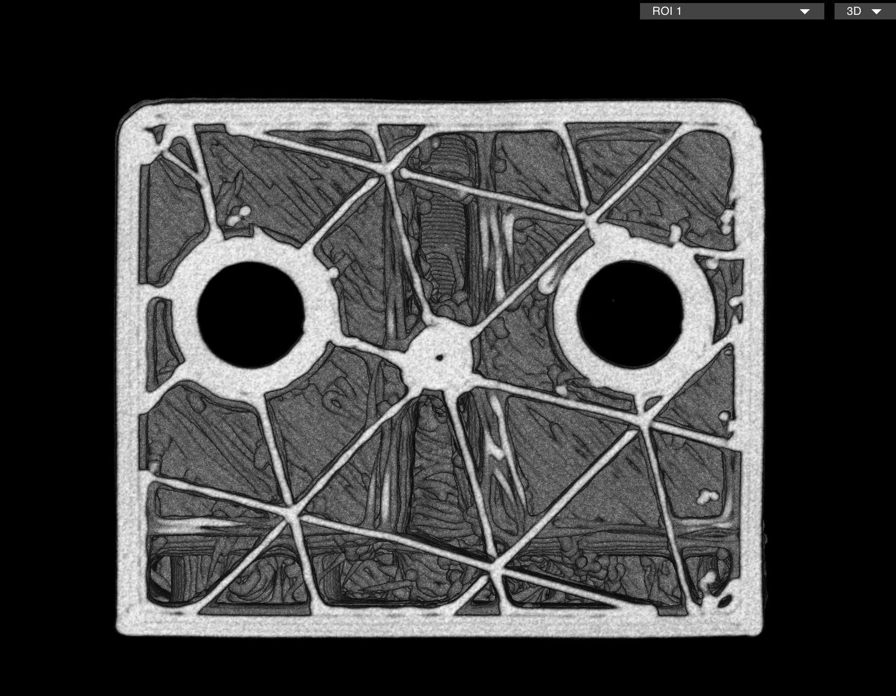
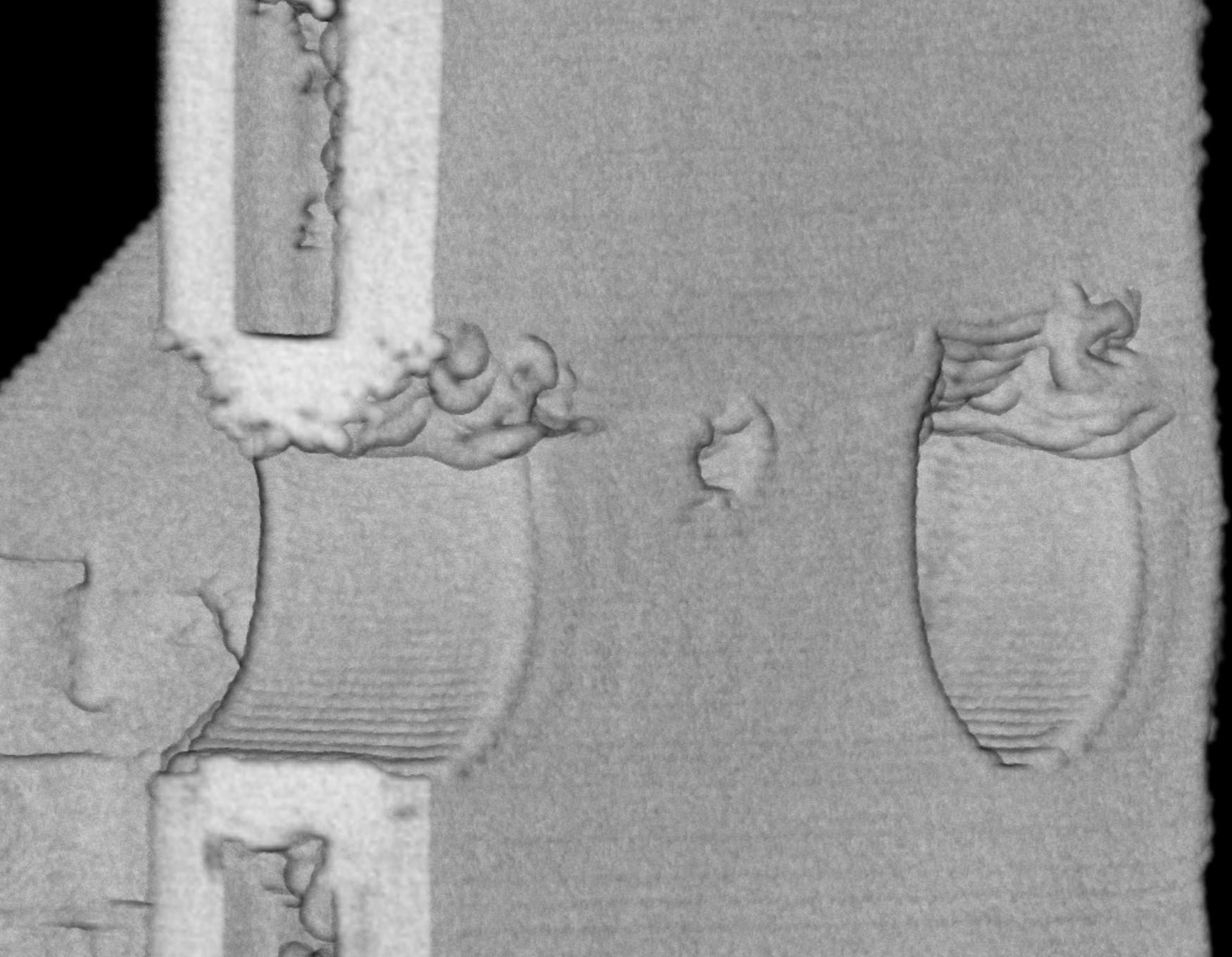
Cropping into our CT scan, we can see the unfused ends of the extruded beads deposited by the printer. Above the holes is evidence of insufficient support during printing: these layers are aesthetically rough, but they are also not fully adhered to each other, possibly creating a structural problem.
Internal features

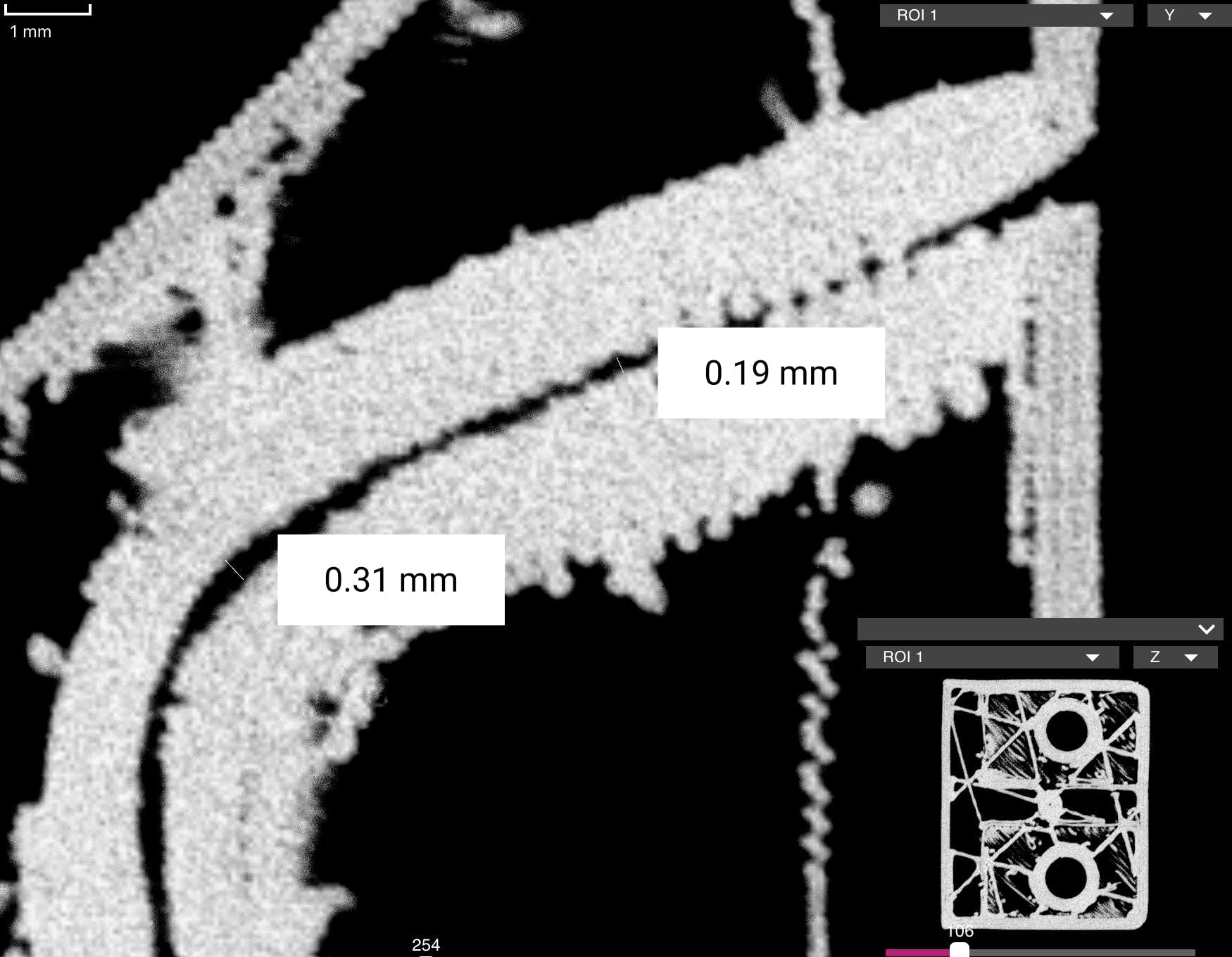
This part was designed with a smooth channel 1 mm in diameter. The FDM printer created a significantly narrower channel with a rough profile—a problem that's outwardly invisible, but could render the part useless.
Other Articles in the Series

  • Homepage: Inspect 3D printed parts with industrial CT
  • Selective Laser Sintering (SLS)
  • Stereolithography (SLA)
  • Multi Jet Fusion (MJF)
  • Direct Metal Laser Sintering (DMLS)

‍

Resource
Article

Inspecting FDM 3D prints with industrial CT

August 1, 2022
Resource

Inspecting FDM 3D prints with industrial CT

Introduction to FDM

Fused deposition modeling (FDM) is one of the earliest forms of 3D printing. FDM printers use one or more heated nozzles to melt and extrude thermoplastic filament, depositing it layer by layer to form a part. FDM printers are common in a wide range of applications, from hobbyist workshops to heavy industry.

As with all 3D printing processes, getting the best results from FDM requires some specialized design knowledge and an understanding of its limitations. An industrial X-ray CT scanner can quickly pinpoint invisible features in FDM prints, including some that can cause failures.

Explore this CT scan in Voyager by creating a free account.

Internal supports

In order to save time and material, operators often configure FDM printers to fill large volumes with a sparse pattern. Here our CT scan reveals a honeycomb lattice inside the solid walls of the part.

Layer quality

Cropping into our CT scan, we can see the unfused ends of the extruded beads deposited by the printer. Above the holes is evidence of insufficient support during printing: these layers are aesthetically rough, but they are also not fully adhered to each other, possibly creating a structural problem.

Internal features

This part was designed with a smooth channel 1 mm in diameter. The FDM printer created a significantly narrower channel with a rough profile—a problem that's outwardly invisible, but could render the part useless.

Other Articles in the Series

  • Homepage: Inspect 3D printed parts with industrial CT
  • Selective Laser Sintering (SLS)
  • Stereolithography (SLA)
  • Multi Jet Fusion (MJF)
  • Direct Metal Laser Sintering (DMLS)
‍

Voyager Inspection Workflows
Introduction to Voyager
Introduction to Neptune
Introduction to Industrial CT
Introducing Mars for 100% Production Inspection
Advancing Automotive Inspection: Industrial CT for Better Outcomes
Introducing Neptune Performance and Triton Performance
Manufacturers Know Quality Costs Money. Most Don't Know How Much.
The Real Cost of a Product Recall and How to Prevent One
What Industrial CT Scanning Does for Manufacturing Quality
Explore more posts
Skip to main content
Mars: In-line arrayed X-ray system >
Platform
Solutions
All Industries
Aerospace and Defense
Agriculture and Food
Athletic Equipment
Automotive
Batteries
Consumer Packaged Goods
Electronics
Medical Devices
Applications
Resources
White Papers
Case Studies
Webinars
Blog
Insights from lumafield
Go/No-Go
Manufacturing podcast
First Article
Editorial Publication
Company
About
Careers
Press
Events
Launch Voyager
Contact Sales
Menu
PlatformSolutions
Industries
All Industries
Agriculture and Food
Electronics
Aerospace and Defense
Automotive
Athletic Equipment
Consumer Packaged Goods
Medical Devices
Batteries
Applications
Resources
Resources
White Papers
Case Studies
Webinars
Blog
Go/No-Go Podcast
First Article
Company
Company
About
Careers
Press
Events
Contact Sales
Launch Voyager
© 2000 Lumafield. All Rights Reserved.
changing the way
the world makes
everything
Solutions
Aerospace and Defense
Agriculture and Food
Athletic Equipment
Automotive
Batteries
Consumer Packaged Goods
Electronics
Medical Devices
All Industries
Applications
Assembly Verification
Competitive Benchmarking and Analysis
Defect Detection
Design Verification and Validation
Dimensional Measurement
Failure Analysis
First Article Inspection (FAI)
Material Characterization
Non-Destructive Testing (NDT)
Quality Assurance and Control (QA & QC)
Reverse Engineering
Supplier Qualification
All Applications
Products
NeptuneTritonVoyagerMars
Resources
LearnFirst ArticleWhite PapersEventsWebinarsSupportCase StudiesCT 101Engineers' Blog
Company
LoginAboutCareersPressBlogContact

Sign up for our newsletter

info@lumafield.com
PrivacyInformation SecurityDeployment Services Agreement
© 2000 Lumafield. All Rights Reserved.