Medical connector compendium
In hospitals, medical connectors are more than mere links; they’re lifelines that must perform flawlessly every time. Miniature marvels of engineering, these components have to withstand rigorous sanitation processes and repeated use. But beneath the seemingly straightforward function of attaching one tube to another, we discover a world of complexity rife with potential manufacturing pitfalls.
Let’s take a look inside a few different types of connectors with our Neptune industrial X-ray CT scanner to learn how they work and where they can sometimes fail.
Luer lock
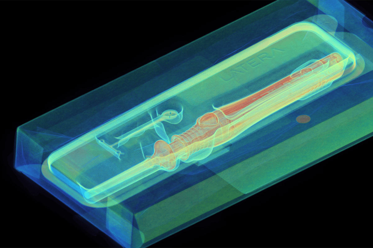
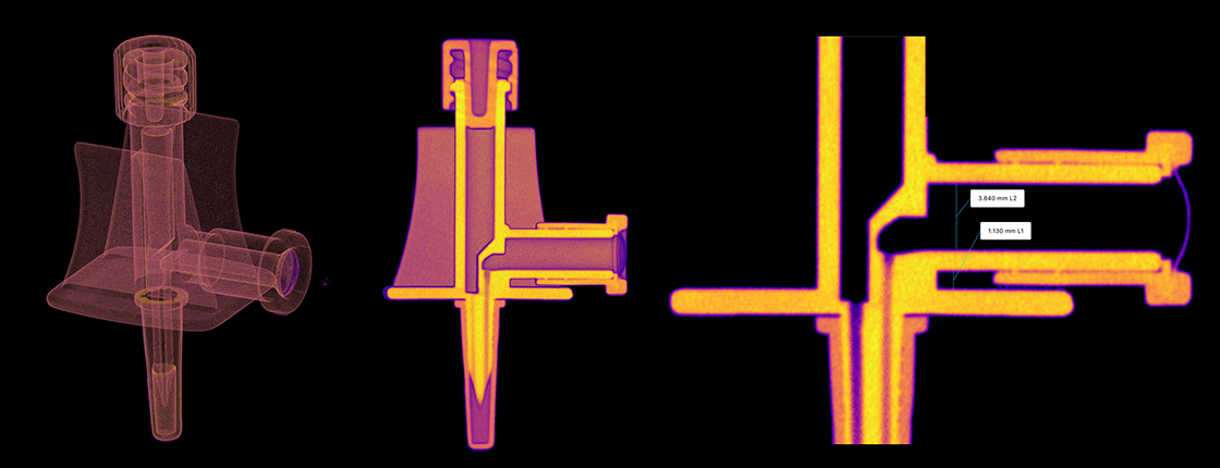
Luer locks work by a twist-and-lock mechanism, securely joining two parts to ensure a leak-free flow of liquids or gasses. In this scan, we can see the external fitting and a cross-sectional view of the interlocking mechanism. If we zoom in, we can find that mechanical stress at the joint has caused a thread to break. By examining cross-sections from any angle using Voyager’s Revolving Slice Plane tool, engineers can detect even the slightest propagation of a crack that could have serious consequences.
T connectors
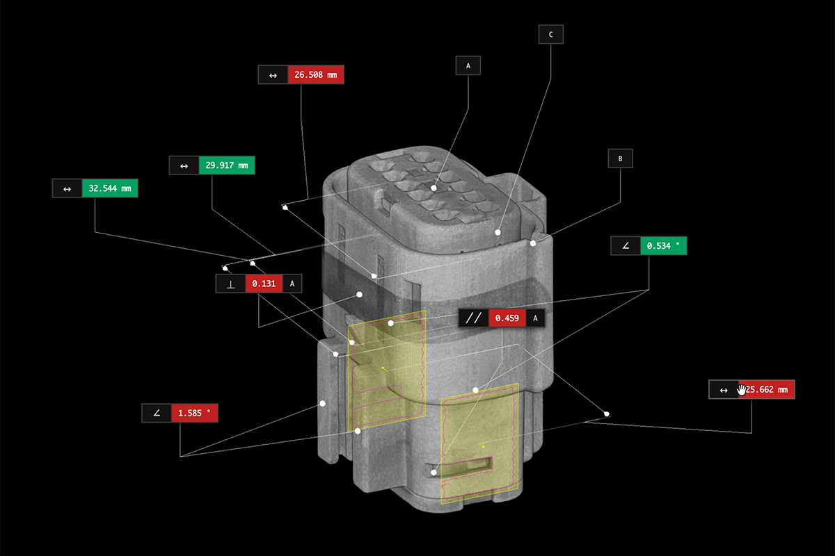
A T connector splits fluid flow into two separate channels. Our CT scan shows a transparent view of the connector's edges, and cropping halfway in, we can visualize its internal pathways. For medical connectors, every micron matters. Industrial CT offers a non-destructive way to verify dimensions within assembled parts. In Voyager, virtual slicing and intact measurements help ensure the utmost dimensional accuracy.
Double hemostasis valve Y connector
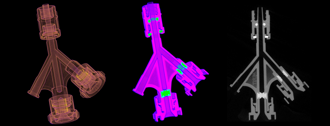
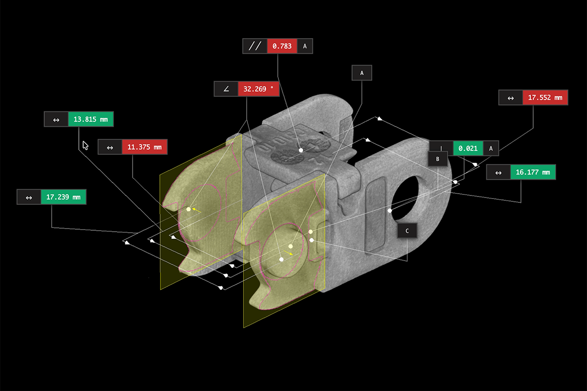
This double hemostasis valve Y connector controls the flow of fluids during procedures while preventing blood loss and air embolism. It also allows simultaneous infusion and intervention through its multiple ports. In the scan image, we see the main Y-body that splits the flow, hemostasis valves on the bottom ends to prevent backflow, a rotating male Luer lock on top for secure attachment, a sideport for additional access, and seals and O-rings that ensure a tight and leak-proof seal. Assembly verification is key for this labyrinth of valves and seals, each with tight tolerances and no room for error.
Luer activated valves
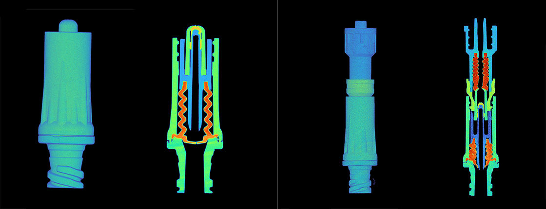
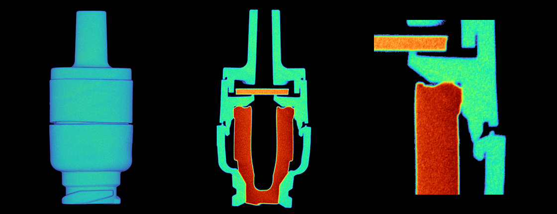
Luer activated valves open to allow fluid flow only when connected to a matching Luer syringe or fitting; they close automatically when disconnected, preventing contamination and leakage. These cross-sectional views show the internal valve stem, seal, and accordion-shaped spacers that control the opening and closing. Each component has a different density with a corresponding color within Voyager’s X-ray attenuation range map. By eliminating the need for destructive testing, not only does CT preserve the functionality of the valve for further use, engineers can confirm successful mating that permits two-way flow while resisting back pressure.
3-way stopcock
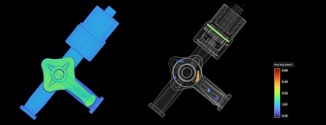
A 3-way stopcock is a valve used to control the flow of fluids or gases through three ports, allowing direction to multiple pathways from a single source. In the scan we see the internal pathways and the lever mechanism. Voyager’s porosity analysis quantifies and visualizes the size and distribution of voids within the lever, ensuring that engineers are informed of potential weaknesses in the injection-molding manufacturing process.
Aseptic connector
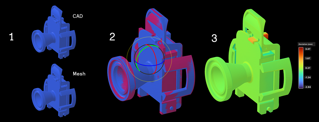
An aseptic connector is designed to ensure a sterile connection, preventing microbial contamination during the transfer of fluids in medical and biopharmaceutical applications. It works by creating a secure and clean link between two separate fluid systems without the need for traditional sterilization methods. Ensuring parts like these match their design down to the last detail is critical. The CAD Comparison tool in Voyager makes it easy for engineers to see how a physical object diverges from its original design. The process is simple: 1) Import a CAD file, and extract a mesh from the scanned part. 2) Align them with Voyager’s auto-alignment feature. 3) Compare the overlaid parts with a heat map to quickly visualize and quantify any deviations.
Conclusion
Every spiral in a thread, every snug fit of a joint, and the uncompromising accuracy of their dimensions speak to high stakes and even higher precision that define these connectors. Here, defects aren’t just imperfections; they’re harbingers of critical failures that could compromise healthcare outcomes. With industrial CT, manufacturers can deliver the highest-quality components possible to the medical professionals and patients who depend on them.
Learn more
Despite obtaining FDA approval, approximately 4,500 medical devices are removed from shelves every year due to previously undetected defects. Download our free white paper The Engineer's Guide to Medical Device Defects to learn how industrial x-ray CT can help prevent these recalls and ensure patient safety.