FREE WHITE PAPER

Heading

Date
This is some text inside of a div block.
FREE WHITE PAPER

Heading 1

Heading 2

Heading 3

Heading 4

Heading 5
Heading 6

Lorem ipsum dolor sit amet, consectetur adipiscing elit, sed do eiusmod tempor incididunt ut labore et dolore magna aliqua. Ut enim ad minim veniam, quis nostrud exercitation ullamco laboris nisi ut aliquip ex ea commodo consequat. Duis aute irure dolor in reprehenderit in voluptate velit esse cillum dolore eu fugiat nulla pariatur.

Block quote

Ordered list

  1. Item 1
  2. Item 2
  3. Item 3

Unordered list

  • Item A
  • Item B
  • Item C

Text link

Bold text

Emphasis

Superscript

Subscript

Heading 1

Heading 2

Heading 3

Heading 4

Heading 5
Heading 6

Lorem ipsum dolor sit amet, consectetur adipiscing elit, sed do eiusmod tempor incididunt ut labore et dolore magna aliqua. Ut enim ad minim veniam, quis nostrud exercitation ullamco laboris nisi ut aliquip ex ea commodo consequat. Duis aute irure dolor in reprehenderit in voluptate velit esse cillum dolore eu fugiat nulla pariatur.

Block quote

Ordered list

  1. Item 1
  2. Item 2
  3. Item 3

Unordered list

  • Item A
  • Item B
  • Item C

Text link

Bold text

Emphasis

Superscript

Subscript

Download Resource
Thank you! Your submission has been received!
Oops! Something went wrong while submitting the form.

Manufacturing Process: Injection Molding

Edited by
Date
October 3, 2024
What is Injection Molding?

Look around; chances are something within your reach has been injection-molded. Plastic injection molding is one of the most widely used manufacturing processes, capable of producing a staggering range of parts with high precision, speed, and efficiency. 

The process involves injecting molten plastic into a mold to create complex parts in large volumes, making it ideal for many of the items we use and depend on every day. With its ability to reliably form almost any part with tight tolerances, injection molding has become the go-to method for manufacturing both simple and intricate components.
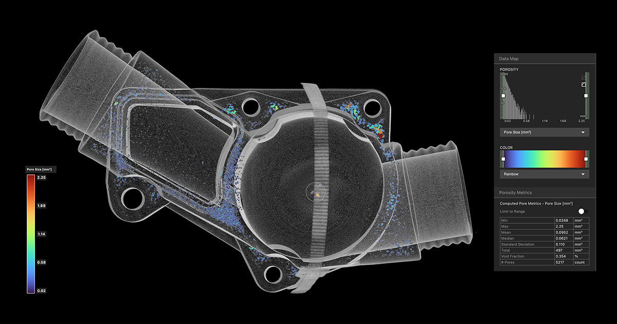
Lumafield’s automated Porosity Analysis tool visualizes and quantifies internal voids within injection molded parts. In Voyager, you can see a range of metrics and measure pores by size, sphericity, and proximity to the surface.

One of the key benefits of plastic injection molding is its scalability. Once the mold is created, manufacturers can produce thousands—or even millions—of identical parts quickly and consistently. Plastic injection molding supports a wide variety of thermoplastic materials, each with specific properties such as durability, stiffness, or heat resistance, allowing manufacturers to tailor parts to their exact needs.

But plastic injection molding is not without its drawbacks. Designing an efficient mold is critical to avoiding common issues such as warping, shrinkage, or internal voids. The upfront cost of creating molds can also be high, though these costs are often offset by lower per-part costs in large production runs. The ability to balance design, material selection, and process control is crucial to achieving high-quality results.

The Plastic Injection Molding Process
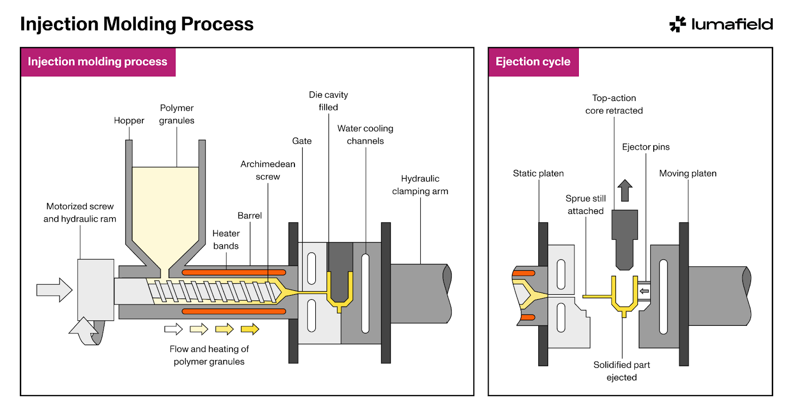
The plastic injection molding process can be broken down into the following steps:

  1. Material Selection: The process begins with selecting the appropriate thermoplastic material, such as ABS, Polypropylene, or Nylon. Material choice depends on factors such as strength, stiffness, heat resistance, and the intended application of the final part.
  2. Shot Preparation: Pelletized material is fed into the barrel of the injection molding machine, where it’s melted through a combination of zoned heating and pressure from the injection screw..
  3. Injection: The molten plastic is injected at high pressure into a metal mold designed to form the shape of the final part. The injection phase is crucial because it determines the accuracy of the part’s dimensions and features.
  4. Cooling: After injection, the injected resin cools and solidifies into its final shape. The cooling rate must be carefully controlled to prevent defects like warping or sink marks. Uneven cooling can lead to internal stresses that may affect the part’s strength or appearance.
  5. Ejection: Once the plastic has solidified, the mold opens, and the part is ejected using pins or other mechanisms. The part may require minimal post-processing, such as trimming excess material, before it’s ready for use.

Plastic injection molding is highly efficient, especially for large production volumes. However, achieving consistent quality requires careful control over variables like material temperature, injection pressure, and cooling rates. Poor control can lead to defects, such as short shots (where the mold isn’t fully filled) or flash (excess material at parting lines).
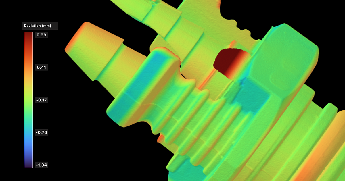
Voyager’s CAD Comparison tool allows you to overlay your design file and manufactured part to calculate deviations. Here, CAD Comparison has identified flash (in red) on an injection-molded hose barb, an indicator that quality parameters need to be revisited.
What is Overmolding?

Overmolding is a process within injection molding where one material is molded over a previously molded part, typically made of a different material. This technique allows manufacturers to create multi-material parts that combine different textures, colors, or functions. Overmolding is especially useful for parts such as handles that require a combination of rigidity and flexibility, or where adding a soft, ergonomic surface to a hard plastic core improves usability.

The Overmolding Process:
  1. Base Part Molding: The process starts with molding the base part, usually from a rigid plastic material like ABS or Nylon. This part serves as the foundation onto which the second material will be applied.
  2. Placement into a Secondary Mold: Once the base part has cooled and solidified, it is placed into a secondary mold that forms and applies the second material. This mold is shaped to cover specific areas of the base part, ensuring that only the intended sections are coated.
  3. Injection of the Second Material: The second material, often a softer plastic or rubber-like thermoplastic elastomer (TPE), is injected over the base part. This second material bonds to the base during the injection, creating a strong adhesion between the two layers.
  4. Cooling and Ejection: After the second material has been injected and properly shaped, the part is cooled and ejected from the mold. The final result is a multi-material product that integrates the best properties of both materials.

Overmolding is widely used to improve product functionality and aesthetics. For example, in consumer electronics, it can provide better grip or insulation, while in medical devices, it adds ergonomic benefits and soft-touch surfaces. By combining materials, overmolding enhances both the performance and usability of the final product.
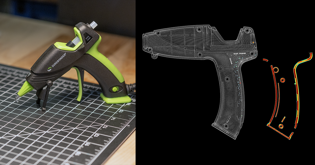
This overmolded glue gun handle is rife with internal porosity within the overmolded plastic. Voyager also allows you to examine layer adhesion between the base part and secondary material.
Design Considerations for Injection Molding

Design for Manufacturability (DFM) is crucial when developing parts for injection molding. Proper design ensures that the mold functions efficiently, minimizes defects, and keeps production costs low.

  • Part Geometry: Uniform wall thickness is a fundamental principle in injection molding design. Variations in thickness can lead to defects such as warping or sink marks because different section thicknesses cool at different rates. Complex features, such as ribs or undercuts, must be carefully designed to avoid trapping air or causing incomplete filling during the injection process.
  • Draft Angles: Including draft angles in the design allows for easy ejection of the part from the mold. Without sufficient draft, parts can get stuck in the mold, leading to surface defects or damage. The recommended draft angle varies depending on the material and part geometry but typically ranges from 1 to 3 degrees.
  • Material Flow and Gate Design: Gate placement—the entry point where the plastic flows into the mold—is critical to ensure proper filling and minimize defects like short shots or flow lines. Designers need to ensure that the material flows evenly throughout the mold to avoid incomplete filling or air entrapment.
  • Mold Design and Tooling: The complexity of the mold design impacts the final product’s quality and the overall cost of production. Molds can be single-cavity for simple parts, can feature multiple actions for more complex parts, or can feature many cavities for high-volume production. Cooling channels must be efficiently designed to ensure uniform cooling and prevent warping or distortion in the final part.
  • Adhesion and Shrinkage: For overmolding, the base material must be designed to bond well with the second material. Designers need to account for different material shrinkage rates and thermal expansion properties to ensure proper adhesion and prevent delamination.
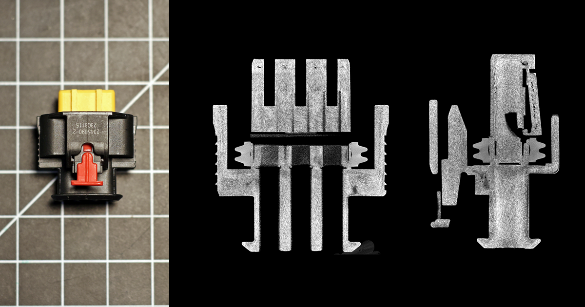
In this Microfocus industrial CT scan, we can assess flow lines and fiber orientation in addition to internal voids within this automotive connector.
How Industrial CT Can Improve Plastic Injection Molding

Industrial computed tomography (CT) scanning has become an invaluable tool in modern manufacturing, providing non-destructive insights that improve both product quality and process efficiency in plastic injection molding. CT scanning addresses several common issues manufacturers face, ensuring precision and reliability.

  • Quality Assurance and Defect Detection: CT scanning detects internal defects like porosity, inclusions, sink marks, or incomplete fills that are invisible with traditional methods. This ensures parts are structurally sound, whether single-material or overmolded, before reaching customers.
  • Dimensional Accuracy and Verification: CT provides precise internal and external measurements, allowing manufacturers to verify that parts meet specifications. This early detection of dimensional variations helps prevent performance issues in both standard injection molding and overmolding applications.
  • Process Optimization: CT scans reveal material flow, cooling rates, and potential issues like air entrapment, allowing manufacturers to fine-tune mold designs, gate placement, and injection speed. This improves overall efficiency and reduces defects across both processes.
  • Mold Validation and Early Prototyping: By scanning prototypes, CT ensures mold designs are correct before full-scale production, reducing costly errors and speeding up the development cycle.
  • Failure Analysis and Troubleshooting: When parts fail in testing or the field, CT enables detailed failure analysis, pinpointing internal defects or material inconsistencies. This helps manufacturers address the root cause of the failure and improve future production runs.
  • Reducing Scrap and Waste: Early detection of defects and optimization of processes through high-speed CT scanning reduces waste, minimizes rework, and improves sustainability, all while lowering material costs.
  • Tooling Maintenance and Wear Monitoring: CT scanning tracks subtle changes in part dimensions or surface quality over time, identifying mold wear and ensuring timely maintenance to prevent defects.
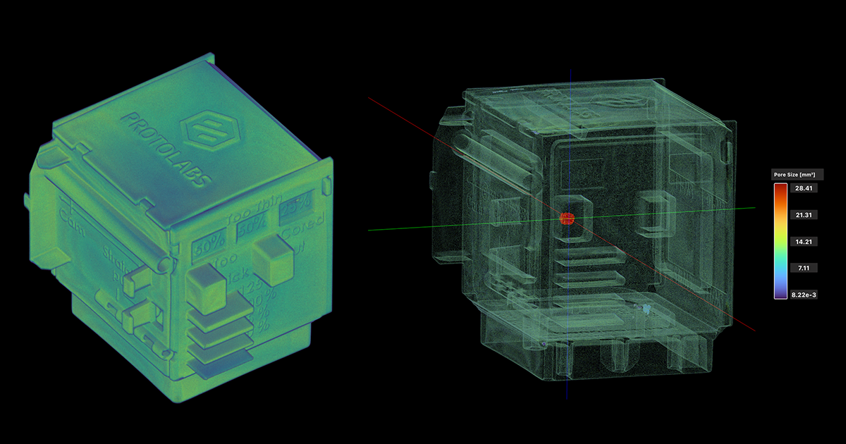
This industrial CT scan of the Protolabs Design Cube demonstrates injection-molded part features that are right and wrong according to a range of criteria. Voyager’s Porosity Analysis pinpoints a large internal void in an area that is too thick.
Conclusion

Plastic injection molding and overmolding are efficient and versatile processes for producing a wide range of parts across all industries. While both present their own design and production challenges, industrial CT provides a key to overcoming these hurdles. By quickly unlocking detailed insights into material flow, dimensional accuracy, and internal defects, CT scanning helps manufacturers improve quality, optimize processes, and reduce waste faster than ever.

Discover how industrial CT can optimize your injection molding process
Resource
Article

Manufacturing Process: Injection Molding

October 3, 2024
Resource

Manufacturing Process: Injection Molding

What is Injection Molding?

Look around; chances are something within your reach has been injection-molded. Plastic injection molding is one of the most widely used manufacturing processes, capable of producing a staggering range of parts with high precision, speed, and efficiency. 

The process involves injecting molten plastic into a mold to create complex parts in large volumes, making it ideal for many of the items we use and depend on every day. With its ability to reliably form almost any part with tight tolerances, injection molding has become the go-to method for manufacturing both simple and intricate components.

Lumafield’s automated Porosity Analysis tool visualizes and quantifies internal voids within injection molded parts. In Voyager, you can see a range of metrics and measure pores by size, sphericity, and proximity to the surface.

One of the key benefits of plastic injection molding is its scalability. Once the mold is created, manufacturers can produce thousands—or even millions—of identical parts quickly and consistently. Plastic injection molding supports a wide variety of thermoplastic materials, each with specific properties such as durability, stiffness, or heat resistance, allowing manufacturers to tailor parts to their exact needs.

But plastic injection molding is not without its drawbacks. Designing an efficient mold is critical to avoiding common issues such as warping, shrinkage, or internal voids. The upfront cost of creating molds can also be high, though these costs are often offset by lower per-part costs in large production runs. The ability to balance design, material selection, and process control is crucial to achieving high-quality results.

The Plastic Injection Molding Process

The plastic injection molding process can be broken down into the following steps:

  1. Material Selection: The process begins with selecting the appropriate thermoplastic material, such as ABS, Polypropylene, or Nylon. Material choice depends on factors such as strength, stiffness, heat resistance, and the intended application of the final part.
  2. Shot Preparation: Pelletized material is fed into the barrel of the injection molding machine, where it’s melted through a combination of zoned heating and pressure from the injection screw..
  3. Injection: The molten plastic is injected at high pressure into a metal mold designed to form the shape of the final part. The injection phase is crucial because it determines the accuracy of the part’s dimensions and features.
  4. Cooling: After injection, the injected resin cools and solidifies into its final shape. The cooling rate must be carefully controlled to prevent defects like warping or sink marks. Uneven cooling can lead to internal stresses that may affect the part’s strength or appearance.
  5. Ejection: Once the plastic has solidified, the mold opens, and the part is ejected using pins or other mechanisms. The part may require minimal post-processing, such as trimming excess material, before it’s ready for use.

Plastic injection molding is highly efficient, especially for large production volumes. However, achieving consistent quality requires careful control over variables like material temperature, injection pressure, and cooling rates. Poor control can lead to defects, such as short shots (where the mold isn’t fully filled) or flash (excess material at parting lines).

Voyager’s CAD Comparison tool allows you to overlay your design file and manufactured part to calculate deviations. Here, CAD Comparison has identified flash (in red) on an injection-molded hose barb, an indicator that quality parameters need to be revisited.
What is Overmolding?

Overmolding is a process within injection molding where one material is molded over a previously molded part, typically made of a different material. This technique allows manufacturers to create multi-material parts that combine different textures, colors, or functions. Overmolding is especially useful for parts such as handles that require a combination of rigidity and flexibility, or where adding a soft, ergonomic surface to a hard plastic core improves usability.

The Overmolding Process:
  1. Base Part Molding: The process starts with molding the base part, usually from a rigid plastic material like ABS or Nylon. This part serves as the foundation onto which the second material will be applied.
  2. Placement into a Secondary Mold: Once the base part has cooled and solidified, it is placed into a secondary mold that forms and applies the second material. This mold is shaped to cover specific areas of the base part, ensuring that only the intended sections are coated.
  3. Injection of the Second Material: The second material, often a softer plastic or rubber-like thermoplastic elastomer (TPE), is injected over the base part. This second material bonds to the base during the injection, creating a strong adhesion between the two layers.
  4. Cooling and Ejection: After the second material has been injected and properly shaped, the part is cooled and ejected from the mold. The final result is a multi-material product that integrates the best properties of both materials.

Overmolding is widely used to improve product functionality and aesthetics. For example, in consumer electronics, it can provide better grip or insulation, while in medical devices, it adds ergonomic benefits and soft-touch surfaces. By combining materials, overmolding enhances both the performance and usability of the final product.

This overmolded glue gun handle is rife with internal porosity within the overmolded plastic. Voyager also allows you to examine layer adhesion between the base part and secondary material.
Design Considerations for Injection Molding

Design for Manufacturability (DFM) is crucial when developing parts for injection molding. Proper design ensures that the mold functions efficiently, minimizes defects, and keeps production costs low.

  • Part Geometry: Uniform wall thickness is a fundamental principle in injection molding design. Variations in thickness can lead to defects such as warping or sink marks because different section thicknesses cool at different rates. Complex features, such as ribs or undercuts, must be carefully designed to avoid trapping air or causing incomplete filling during the injection process.
  • Draft Angles: Including draft angles in the design allows for easy ejection of the part from the mold. Without sufficient draft, parts can get stuck in the mold, leading to surface defects or damage. The recommended draft angle varies depending on the material and part geometry but typically ranges from 1 to 3 degrees.
  • Material Flow and Gate Design: Gate placement—the entry point where the plastic flows into the mold—is critical to ensure proper filling and minimize defects like short shots or flow lines. Designers need to ensure that the material flows evenly throughout the mold to avoid incomplete filling or air entrapment.
  • Mold Design and Tooling: The complexity of the mold design impacts the final product’s quality and the overall cost of production. Molds can be single-cavity for simple parts, can feature multiple actions for more complex parts, or can feature many cavities for high-volume production. Cooling channels must be efficiently designed to ensure uniform cooling and prevent warping or distortion in the final part.
  • Adhesion and Shrinkage: For overmolding, the base material must be designed to bond well with the second material. Designers need to account for different material shrinkage rates and thermal expansion properties to ensure proper adhesion and prevent delamination.
In this Microfocus industrial CT scan, we can assess flow lines and fiber orientation in addition to internal voids within this automotive connector.
How Industrial CT Can Improve Plastic Injection Molding

Industrial computed tomography (CT) scanning has become an invaluable tool in modern manufacturing, providing non-destructive insights that improve both product quality and process efficiency in plastic injection molding. CT scanning addresses several common issues manufacturers face, ensuring precision and reliability.

  • Quality Assurance and Defect Detection: CT scanning detects internal defects like porosity, inclusions, sink marks, or incomplete fills that are invisible with traditional methods. This ensures parts are structurally sound, whether single-material or overmolded, before reaching customers.
  • Dimensional Accuracy and Verification: CT provides precise internal and external measurements, allowing manufacturers to verify that parts meet specifications. This early detection of dimensional variations helps prevent performance issues in both standard injection molding and overmolding applications.
  • Process Optimization: CT scans reveal material flow, cooling rates, and potential issues like air entrapment, allowing manufacturers to fine-tune mold designs, gate placement, and injection speed. This improves overall efficiency and reduces defects across both processes.
  • Mold Validation and Early Prototyping: By scanning prototypes, CT ensures mold designs are correct before full-scale production, reducing costly errors and speeding up the development cycle.
  • Failure Analysis and Troubleshooting: When parts fail in testing or the field, CT enables detailed failure analysis, pinpointing internal defects or material inconsistencies. This helps manufacturers address the root cause of the failure and improve future production runs.
  • Reducing Scrap and Waste: Early detection of defects and optimization of processes through high-speed CT scanning reduces waste, minimizes rework, and improves sustainability, all while lowering material costs.
  • Tooling Maintenance and Wear Monitoring: CT scanning tracks subtle changes in part dimensions or surface quality over time, identifying mold wear and ensuring timely maintenance to prevent defects.
This industrial CT scan of the Protolabs Design Cube demonstrates injection-molded part features that are right and wrong according to a range of criteria. Voyager’s Porosity Analysis pinpoints a large internal void in an area that is too thick.
Conclusion

Plastic injection molding and overmolding are efficient and versatile processes for producing a wide range of parts across all industries. While both present their own design and production challenges, industrial CT provides a key to overcoming these hurdles. By quickly unlocking detailed insights into material flow, dimensional accuracy, and internal defects, CT scanning helps manufacturers improve quality, optimize processes, and reduce waste faster than ever.

Discover how industrial CT can optimize your injection molding process
Voyager Inspection Workflows
Introduction to Voyager
Introduction to Neptune
Introduction to Industrial CT
Advancing Automotive Inspection: Industrial CT for Better Outcomes
Introducing Neptune Performance and Triton Performance
Manufacturers Know Quality Costs Money. Most Don't Know How Much.
The Real Cost of a Product Recall and How to Prevent One
What Industrial CT Scanning Does for Manufacturing Quality
Next-Generation Drones: Protecting Performance with Industrial CT
Explore more posts
メインコンテンツへスキップ
New Performance scanners are here >
プラットフォーム
分野別ソリューション
すべての業界
バッテリー
医療機器
消費財
スポーツ用品
自動車
航空宇宙/防衛
農業と食品
電子機器
用途別アプリケーション
各種資料
技術資料
ケーススタディ
オンラインセミナー
Blog
Insights from lumafield
Go/No-Go
Manufacturing podcast
First Article
Editorial Publication
企業情報
会社概要
採用情報
プレスリリース
Events
Voyager を起動
お問い合わせはこちら
メニュー
製品業界
業界
すべての業界
電子機器
医療機器
自動車
消費財
バッテリー
農業と食品
航空宇宙/防衛
スポーツ用品
[アプリケーション]
リソース
リソース
ホワイトペーパー
101
オンラインセミナー
最初の記事
Go/No-Go Podcast
First Article
会社
会社
について
採用情報
プレス
Events
セールスに問い合わせる
ボイジャーを起動
© 2000 Lumafield. All Rights Reserved.
世界の”ものづくり”を変える。
分野別ソリューション
バッテリー
医療機器
消費財
スポーツ用品
自動車
航空宇宙/防衛
農業と食品
電子機器
すべての業界
用途別アプリケーション
リバースエンジニアリング
ファースト・アーティクル・インスペクション (FAI)
品質保証と品質管理
寸法測定
故障解析
材料特性評価
欠陥検出
競合ベンチマークと分析
組み立て検証
設計検証と妥当性の確認
サプライヤー適格性評価
非破壊検査 (NDT)
すべてのアプリケーション
製品
ネプチューントリトンボイジャーアトラス
各種資料
学習コンテンツメディア技術資料ウェビナーオンラインセミナー初回CTスキャン分析ガイドケーススタディCT入門エンジニアブログ
企業情報
ログイン会社概要採用情報プレスリリースブログお問い合わせ

ニュースレターに登録する

info@lumafield.com
プライバシー情報セキュリティ導入サービス契約
© 2000 ルマフィールド。全著作権所有。