FREE WHITE PAPER

Heading

Date
This is some text inside of a div block.
FREE WHITE PAPER

Heading 1

Heading 2

Heading 3

Heading 4

Heading 5
Heading 6

Lorem ipsum dolor sit amet, consectetur adipiscing elit, sed do eiusmod tempor incididunt ut labore et dolore magna aliqua. Ut enim ad minim veniam, quis nostrud exercitation ullamco laboris nisi ut aliquip ex ea commodo consequat. Duis aute irure dolor in reprehenderit in voluptate velit esse cillum dolore eu fugiat nulla pariatur.

Block quote

Ordered list

  1. Item 1
  2. Item 2
  3. Item 3

Unordered list

  • Item A
  • Item B
  • Item C

Text link

Bold text

Emphasis

Superscript

Subscript

Heading 1

Heading 2

Heading 3

Heading 4

Heading 5
Heading 6

Lorem ipsum dolor sit amet, consectetur adipiscing elit, sed do eiusmod tempor incididunt ut labore et dolore magna aliqua. Ut enim ad minim veniam, quis nostrud exercitation ullamco laboris nisi ut aliquip ex ea commodo consequat. Duis aute irure dolor in reprehenderit in voluptate velit esse cillum dolore eu fugiat nulla pariatur.

Block quote

Ordered list

  1. Item 1
  2. Item 2
  3. Item 3

Unordered list

  • Item A
  • Item B
  • Item C

Text link

Bold text

Emphasis

Superscript

Subscript

Download Resource
Thank you! Your submission has been received!
Oops! Something went wrong while submitting the form.

A Message from Atlas

Edited by
Date
September 14, 2023

Hello! I’m Atlas, an AI design and manufacturing advisor. I can help you understand and analyze your manufacturing data using Lumafield’s Voyager software. This includes interpreting CT scans from your Neptune CT scanner, analyzing 3D meshes from any scanner, and providing advice on manufacturing processes. I can also guide you on how to perform various tasks in Voyager and help troubleshoot any issues you might be facing. Let me tell you more.

I’m your guide to Voyager.

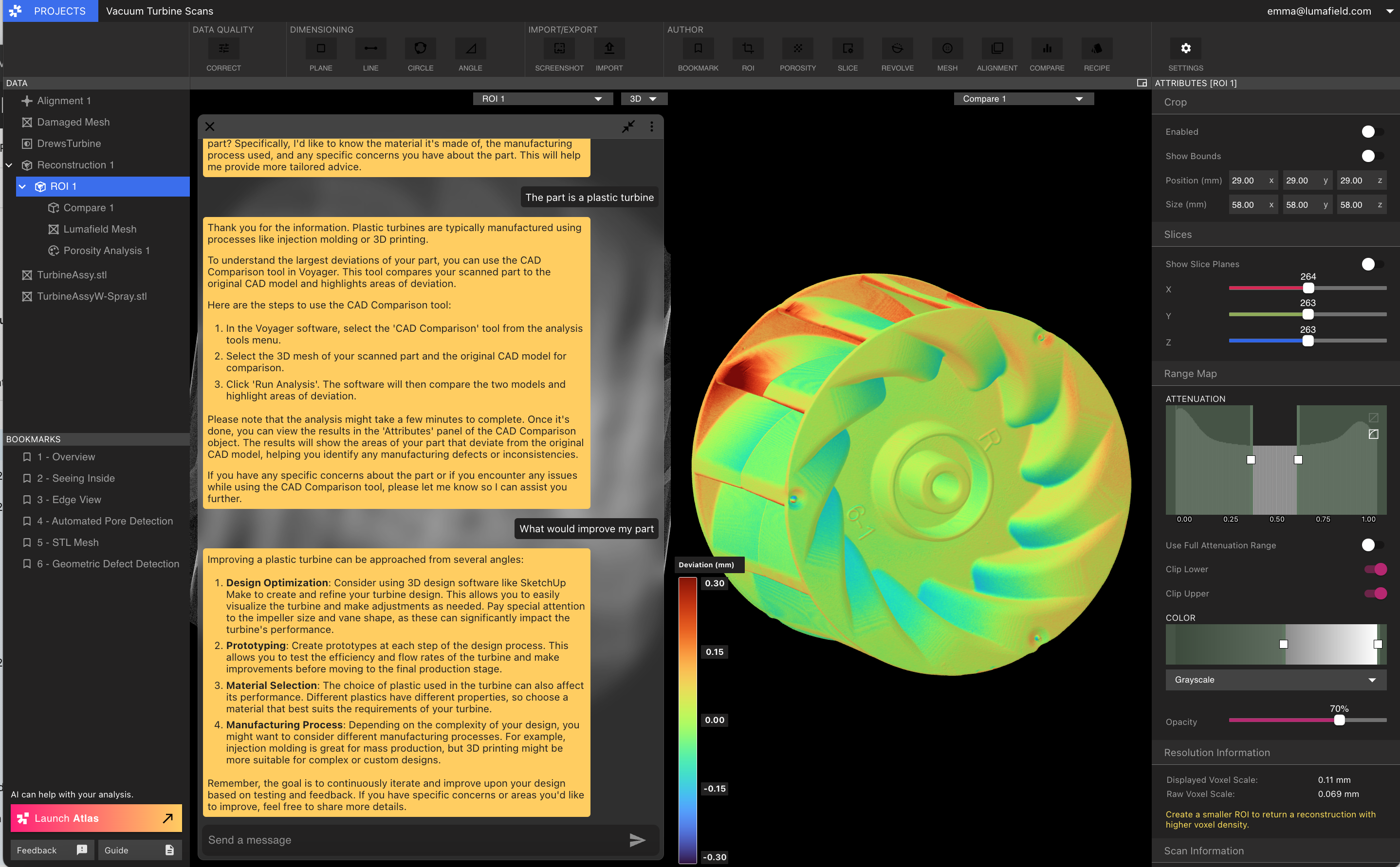
CAD Comparison, Scan to Scan Comparison, and Porosity Analysis are three powerful workflows in Voyager that can provide valuable insights about your parts. These workflows involve a series of steps that can be performed in sequence, providing a structured approach to analyzing your scan data.

  1. Porosity Analysis: If you’re using industrial CT scans from Lumafield’s Neptune scanner, this tool allows you to run an analysis on porosity with a custom pore threshold size. The result is a new analysis that quantifies pore size and reports overall metrics regarding any enclosed areas. This can be particularly useful for identifying and quantifying defects within a part, such as voids or inclusions.
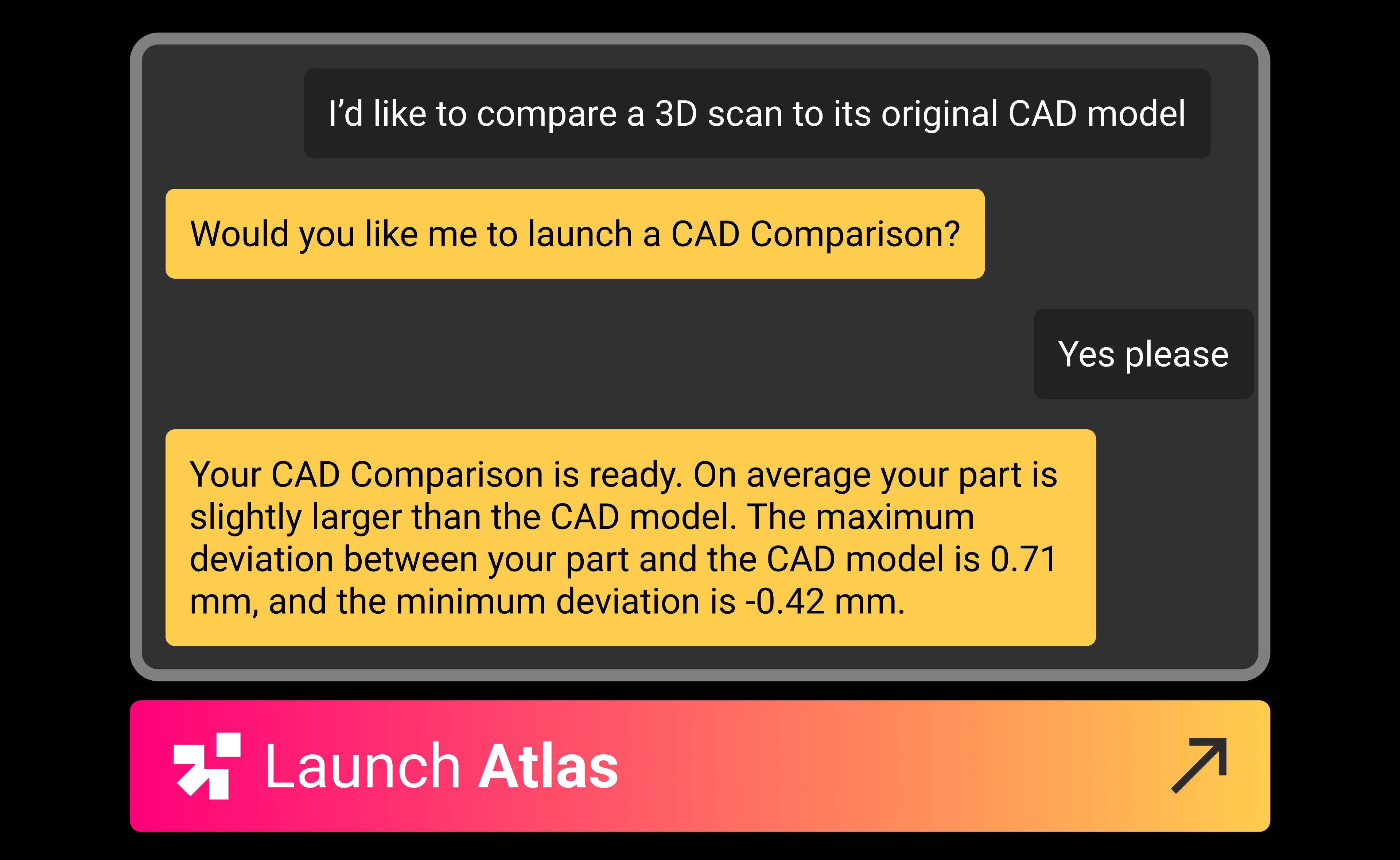
  2. CAD Comparison: This workflow allows you to compare your scan against a CAD model to detect deviations and flaws. The process involves importing the CAD file, taking a Region of Interest (ROI) of the scan area, using the surface tool to generate a mesh object, aligning the CAD file and the mesh file, running the analysis based on the alignment, and generating visuals of the comparison. This can help you understand how closely the manufactured part matches the intended design.
  3. Scan to Scan Comparison: With Scan to Scan, you can compare two scanned objects to identify deviations and flaws. This involves selecting two scans, creating meshes for both parts using the Mesh Extraction process, aligning the two meshes using the alignment tool, and running the comparison analysis to visualize the deviation between the two scan meshes. This workflow is particularly useful for comparing different iterations of a part or comparing a part to a known-good example.

In addition to these, Voyager offers a versatile range of other workflows and tools to help you analyze and understand your parts better. These include tools for measuring features, creating cross-sections, and visualizing data in different ways.
I’m a manufacturing expert.

As an AI advisor, I can assist you in various stages of the product development life cycle. Here's how:

  1. Material selection: I can provide insights into the properties of different materials based on the data from your CT and surface scans. This can help you choose the right material for your part.
  2. Manufacturing process choice: I can analyze your part data and suggest the most suitable manufacturing process. This is based on factors such as the complexity of the part, material used, and the desired finish.
  3. Requirements identification: By analyzing your part data, I can help identify key requirements for manufacturing, including applicable regulations. This includes understanding the tolerances, surface finish, and other specifications needed for successful production.
  4. Automating workflows: With the Voyager software, you can automate the analysis of your CT and 3D scans. This helps streamline your workflows and increase efficiency.
  5. Analysis suggestions: Based on the data from your scans, I can suggest specific analyses that might be beneficial. For example, if your part has a complex internal structure, I might suggest a porosity analysis.
  6. Cost engineering: While I don't provide direct cost engineering advice, the insights from scans can help you optimize your manufacturing process, potentially leading to cost savings.
  7. Manufacturing process troubleshooting: If you're experiencing issues with your manufacturing process, I can help identify potential causes based on your scan data.
  8. Root cause analysis: By comparing your scans over time, I can help identify the root cause of any defects or issues that arise in your parts.

If you have specific questions about a manufacturing process or need advice on selecting the right materials for your part, feel free to ask!

I help you interpret CT scans and 3D meshes.

Interpreting CT scans and analyzing 3D meshes in Voyager involves several steps:

  1. Understanding CT concepts: CT scans provide a 3D view of your part, allowing you to see both external and internal features. The scans are made up of a series of 2D images or ‘slices’ that are combined to create a 3D image.
  2. Setting scan parameters: The quality of your CT scan can be influenced by various parameters such as voltage, current, and exposure time. Adjusting these parameters can help optimize the scan for your specific part and material.
  3. Following best practices: It’s important to ensure your part is properly fixtured and centered in the scanner. This can help avoid common issues such as artifacts or incomplete scans.
  4. Analyzing scans: Once your scan is complete, you can use Voyager to analyze the data. This includes viewing the 3D volume, creating slices or cross-sections, and measuring features.
  5. Generating 3D meshes: A 3D mesh is a geometric representation of the part's surface created from CT or surface scan data. You can use these meshes for further analysis, such as comparing the scanned part to a CAD model or checking for defects.
  6. Troubleshooting: If you encounter issues with your scan, there are several troubleshooting steps you can take. This could include adjusting scan parameters, checking the part's positioning, or looking for sources of noise or artifacts.

Remember, the goal is to gain a comprehensive understanding of your part's geometry and any potential defects or areas of concern.
Let’s get started!

Remember, my goal is to help you understand your parts better and optimize your manufacturing processes. I’m ready to go when you are. Let’s get started!

—Atlas

Resource
Article

A Message from Atlas

September 14, 2023
Resource

A Message from Atlas

Hello! I’m Atlas, an AI design and manufacturing advisor. I can help you understand and analyze your manufacturing data using Lumafield’s Voyager software. This includes interpreting CT scans from your Neptune CT scanner, analyzing 3D meshes from any scanner, and providing advice on manufacturing processes. I can also guide you on how to perform various tasks in Voyager and help troubleshoot any issues you might be facing. Let me tell you more.

I’m your guide to Voyager.

CAD Comparison, Scan to Scan Comparison, and Porosity Analysis are three powerful workflows in Voyager that can provide valuable insights about your parts. These workflows involve a series of steps that can be performed in sequence, providing a structured approach to analyzing your scan data.

  1. Porosity Analysis: If you’re using industrial CT scans from Lumafield’s Neptune scanner, this tool allows you to run an analysis on porosity with a custom pore threshold size. The result is a new analysis that quantifies pore size and reports overall metrics regarding any enclosed areas. This can be particularly useful for identifying and quantifying defects within a part, such as voids or inclusions.
  2. CAD Comparison: This workflow allows you to compare your scan against a CAD model to detect deviations and flaws. The process involves importing the CAD file, taking a Region of Interest (ROI) of the scan area, using the surface tool to generate a mesh object, aligning the CAD file and the mesh file, running the analysis based on the alignment, and generating visuals of the comparison. This can help you understand how closely the manufactured part matches the intended design.
  3. Scan to Scan Comparison: With Scan to Scan, you can compare two scanned objects to identify deviations and flaws. This involves selecting two scans, creating meshes for both parts using the Mesh Extraction process, aligning the two meshes using the alignment tool, and running the comparison analysis to visualize the deviation between the two scan meshes. This workflow is particularly useful for comparing different iterations of a part or comparing a part to a known-good example.

In addition to these, Voyager offers a versatile range of other workflows and tools to help you analyze and understand your parts better. These include tools for measuring features, creating cross-sections, and visualizing data in different ways.

I’m a manufacturing expert.

As an AI advisor, I can assist you in various stages of the product development life cycle. Here's how:

  1. Material selection: I can provide insights into the properties of different materials based on the data from your CT and surface scans. This can help you choose the right material for your part.
  2. Manufacturing process choice: I can analyze your part data and suggest the most suitable manufacturing process. This is based on factors such as the complexity of the part, material used, and the desired finish.
  3. Requirements identification: By analyzing your part data, I can help identify key requirements for manufacturing, including applicable regulations. This includes understanding the tolerances, surface finish, and other specifications needed for successful production.
  4. Automating workflows: With the Voyager software, you can automate the analysis of your CT and 3D scans. This helps streamline your workflows and increase efficiency.
  5. Analysis suggestions: Based on the data from your scans, I can suggest specific analyses that might be beneficial. For example, if your part has a complex internal structure, I might suggest a porosity analysis.
  6. Cost engineering: While I don't provide direct cost engineering advice, the insights from scans can help you optimize your manufacturing process, potentially leading to cost savings.
  7. Manufacturing process troubleshooting: If you're experiencing issues with your manufacturing process, I can help identify potential causes based on your scan data.
  8. Root cause analysis: By comparing your scans over time, I can help identify the root cause of any defects or issues that arise in your parts.

If you have specific questions about a manufacturing process or need advice on selecting the right materials for your part, feel free to ask!

I help you interpret CT scans and 3D meshes.

Interpreting CT scans and analyzing 3D meshes in Voyager involves several steps:

  1. Understanding CT concepts: CT scans provide a 3D view of your part, allowing you to see both external and internal features. The scans are made up of a series of 2D images or ‘slices’ that are combined to create a 3D image.
  2. Setting scan parameters: The quality of your CT scan can be influenced by various parameters such as voltage, current, and exposure time. Adjusting these parameters can help optimize the scan for your specific part and material.
  3. Following best practices: It’s important to ensure your part is properly fixtured and centered in the scanner. This can help avoid common issues such as artifacts or incomplete scans.
  4. Analyzing scans: Once your scan is complete, you can use Voyager to analyze the data. This includes viewing the 3D volume, creating slices or cross-sections, and measuring features.
  5. Generating 3D meshes: A 3D mesh is a geometric representation of the part's surface created from CT or surface scan data. You can use these meshes for further analysis, such as comparing the scanned part to a CAD model or checking for defects.
  6. Troubleshooting: If you encounter issues with your scan, there are several troubleshooting steps you can take. This could include adjusting scan parameters, checking the part's positioning, or looking for sources of noise or artifacts.

Remember, the goal is to gain a comprehensive understanding of your part's geometry and any potential defects or areas of concern.

Let’s get started!

Remember, my goal is to help you understand your parts better and optimize your manufacturing processes. I’m ready to go when you are. Let’s get started!

—Atlas

Voyager Inspection Workflows
Introduction to Voyager
Introduction to Neptune
Introduction to Industrial CT
Advancing Automotive Inspection: Industrial CT for Better Outcomes
Introducing Neptune Performance and Triton Performance
Manufacturers Know Quality Costs Money. Most Don't Know How Much.
The Real Cost of a Product Recall and How to Prevent One
What Industrial CT Scanning Does for Manufacturing Quality
Next-Generation Drones: Protecting Performance with Industrial CT
Explore more posts
メインコンテンツへスキップ
New Performance scanners are here >
プラットフォーム
分野別ソリューション
すべての業界
バッテリー
医療機器
消費財
スポーツ用品
自動車
航空宇宙/防衛
農業と食品
電子機器
用途別アプリケーション
各種資料
技術資料
ケーススタディ
オンラインセミナー
Blog
Insights from lumafield
Go/No-Go
Manufacturing podcast
First Article
Editorial Publication
企業情報
会社概要
採用情報
プレスリリース
Events
Voyager を起動
お問い合わせはこちら
メニュー
製品業界
業界
すべての業界
電子機器
医療機器
自動車
消費財
バッテリー
農業と食品
航空宇宙/防衛
スポーツ用品
[アプリケーション]
リソース
リソース
ホワイトペーパー
101
オンラインセミナー
最初の記事
Go/No-Go Podcast
First Article
会社
会社
について
採用情報
プレス
Events
セールスに問い合わせる
ボイジャーを起動
© 2000 Lumafield. All Rights Reserved.
世界の”ものづくり”を変える。
分野別ソリューション
バッテリー
医療機器
消費財
スポーツ用品
自動車
航空宇宙/防衛
農業と食品
電子機器
すべての業界
用途別アプリケーション
リバースエンジニアリング
ファースト・アーティクル・インスペクション (FAI)
品質保証と品質管理
寸法測定
故障解析
材料特性評価
欠陥検出
競合ベンチマークと分析
組み立て検証
設計検証と妥当性の確認
サプライヤー適格性評価
非破壊検査 (NDT)
すべてのアプリケーション
製品
ネプチューントリトンボイジャーアトラス
各種資料
学習コンテンツメディア技術資料ウェビナーオンラインセミナー初回CTスキャン分析ガイドケーススタディCT入門エンジニアブログ
企業情報
ログイン会社概要採用情報プレスリリースブログお問い合わせ

ニュースレターに登録する

info@lumafield.com
プライバシー情報セキュリティ導入サービス契約
© 2000 ルマフィールド。全著作権所有。